 SynthMaker
The analog switch
An analog switch joins two points or keeps them apart, and a voltage decides which. With a capacitor after it, it grabs a voltage and keeps it: this page builds a sample and hold from one switch: the stepped random voltage that makes a filter jump.
New words
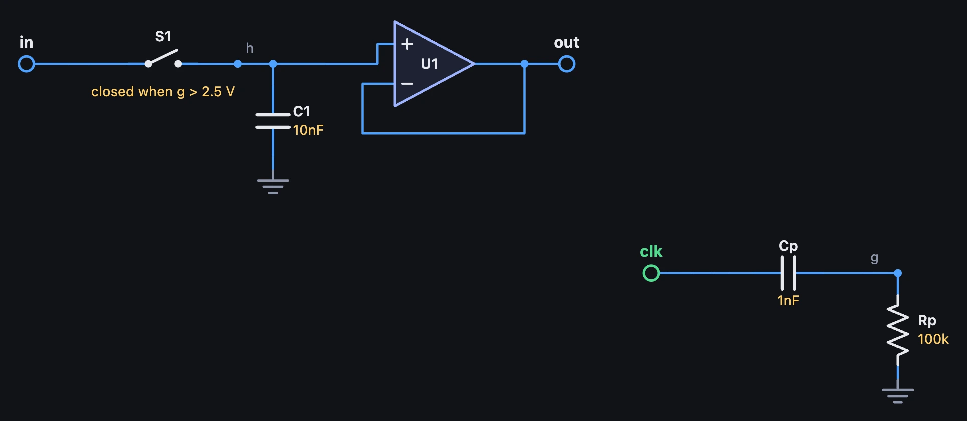
An analog switch is a resistor with two values (S1 a b c+ c-): small while its control voltage is high, huge while it is low.
A track and hold is a switch and a capacitor: while the switch is closed the capacitor follows the input, and when it opens it keeps the last voltage.

1Writing one
Write a switch as S, the two points it joins, then the two points its control voltage is measured between:
S1 a b c+ c- [on 100] [off 100M] [at 2.5V]- While c+ is more than
atvolts above c−, the switch is itsonresistance; otherwise it is itsoffresistance. If you leave them out, they are 100 Ω, 100 MΩ and 2.5 V. - The control takes no current, so it can watch any point without changing it.
- A circuit with a switch runs at 2× unless it says otherwise.
2Track, then hold
A switch and a capacitor make a track and hold: the capacitor follows the input while the switch is closed, and keeps its voltage when it opens. Close it with a square clock, and it follows for half of each cycle and holds for the other half.
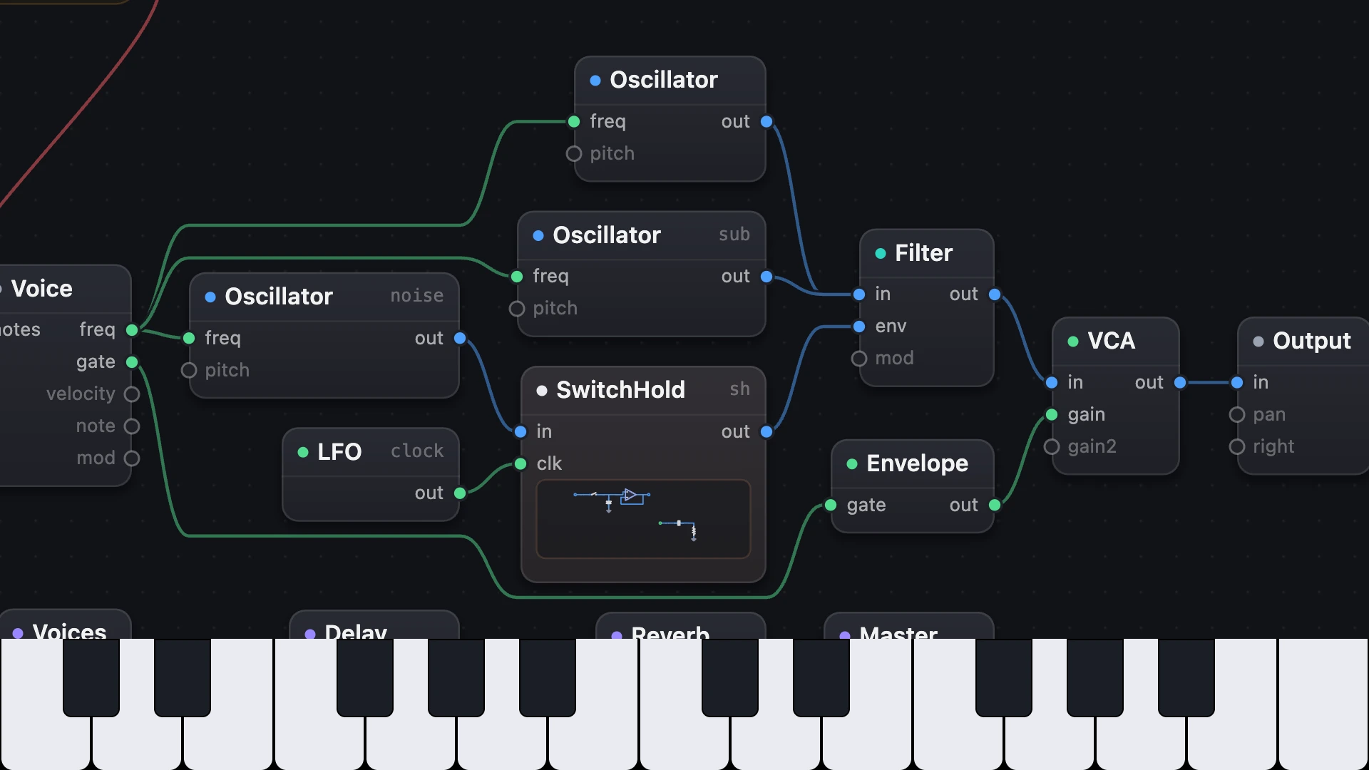
For a sample and hold, close it for just a moment. In Switch Sample and Hold the clock comes through Cp, so only the moment the clock goes high lifts g, and Rp lets it fall back: the switch stays closed for only about 0.14 ms. On each clock it closes for that moment, C1 takes on the noise, and holds it until the next: a new random voltage on every eighth note, wired into a filter. U1 lets the filter read C1 without draining it.
# A sample and hold from one switch. S1 joins the noise at in to C1 while g is over 2.5 V. The clock's square comes# through Cp, so only the clock going high lifts g, and Rp lets it fall back: the switch closes for about 0.14 ms on each# clock, C1 takes on the noise, and holds it until the next. U1 lets the filter read C1 without draining it.circuit SwitchHold setting input: 1 V in clk: from 0 V to 5 V Cp clk g 1n Rp g gnd 100k S1 in h g gnd C1 h gnd 10n U1 h out out opampend3Its limits
- A switch acts where its control crosses
at, even between two samples: SynthMaker takes that step again in pieces, and the switch moves at the crossing. - A circuit holds up to 4 switches, and a comparator written
opencounts as one. - It is ideal: two resistances and nothing else. None of a real switch chip's quirks: no click as it switches, no on resistance that moves with the signal, no gap as it changes over.
Try it
- Open Switch Sample and Hold and hold a low key.
- In the parts list, delete
CpandRpand changeS1 in h g gndtoS1 in h clk gnd: now it tracks the noise for half of every clock, and holds for the other half. - Change
C1 h gnd 10nto10u: the moment is too short to fill it, so the steps get small. - Set the clock's Sync from 1/8 to 1/4: a new step on every beat.
Remember
- A switch is
S1 a b c+ c-: closed while its control voltage is overat, open otherwise. - A switch and a capacitor make a track and hold; close it for a moment and it is a sample and hold.
- A switch acts exactly where its control crosses, so an oscillator reset through one keeps its pitch.