 SynthMaker
Sample and hold
Noise is a random voltage, far too fast to use. A sample and hold grabs what it is at one moment and keeps it until the next: a new random voltage on every clock. Wired into a filter, that's the classic burble. This page builds one from a capacitor, a switch and two op-amps.
New words
A JFET is a transistor used here as a switch: its gate near its other two pins and current flows through it; about 5 V below them and it stops.
Sample and hold: open a switch for a moment so a capacitor takes on a voltage, close it, and the capacitor keeps that voltage.

1A capacitor remembers
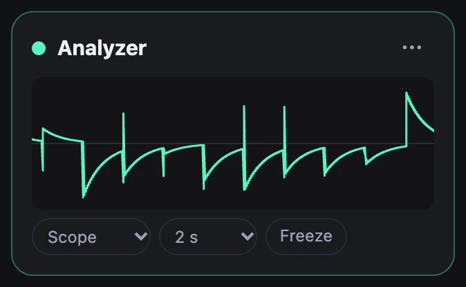
Charge a capacitor, then let go of it, and its voltage stays. A diode shows this with one part: a short pulse from an Envelope charges C1 through D1; when the pulse has gone, the diode stops conducting and nothing can take the charge away.
D1 in out 1N4148
C1 out gnd 1u
To see a voltage that slow, set an Analyzer's Time to 2 s. The trace rolls across, the newest at the right.
2A switch decides when
A JFET is the switch. Write it as J, then its drain, gate and source, as SPICE does:
in gate: from -5 V to 0 V
J1 in g out J111
Rg gate g 100k
C1 out gnd 100n
in gate gives the circuit a second way in. It shows as a port on the box in the Patch, and a wire there is a voltage at a point called gate in the parts list. Written plainly as in gate, a wire's 1.0 is 5 V, as on a modular synth: a gate is 5 V, an LFO swings ±5 V. A range says otherwise: from is the voltage at a wire's 0 and to at its 1. A J111 is on with its gate at 0 V and off at −10 V, so here an LFO's +1 is 0 V and its −1 is −10 V.
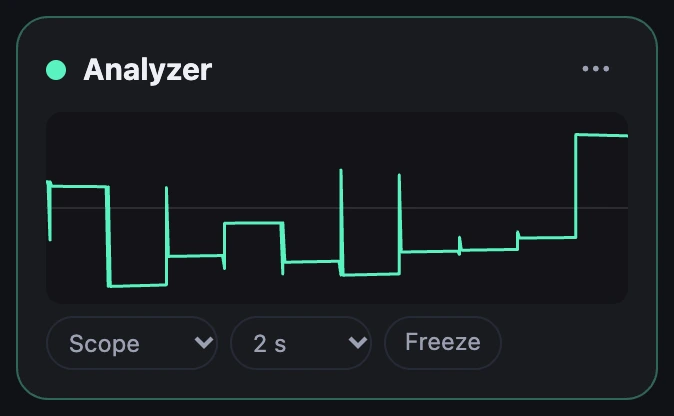
Wire a square LFO into it and the switch is open half the time: the capacitor follows the noise, then holds, then follows. That's a track and hold, not yet what we want.
3Only a moment
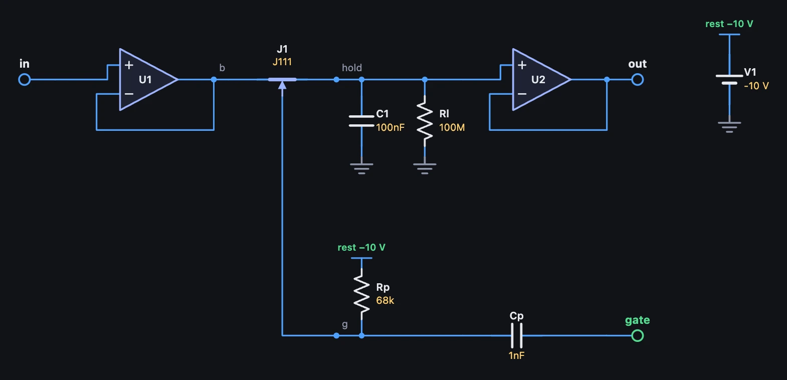
To sample, open the switch only for a moment. The gate rests at −10 V through Rp, well below where it conducts. Now the plain in gate does: the LFO swings from −5 V to +5 V, and it comes through a small capacitor Cp, so only its edges get through. A rising edge is 10 V, which lifts the gate to 0 V, and Rp pulls it back below the point where the switch shuts within about 50 microseconds. Noise becomes steps.
oversample 1x
in gate
V1 rest gnd -10V
Cp gate g 1n
Rp rest g 68k4Why the buffers
Whatever the steps go into draws a little current, and that drains the capacitor. Add a 1M load to show what the next stage takes: 100 nF through 1 MΩ has a time constant of 100 ms, so each step sags away before the next. Put an op-amp in between and the load hangs from the op-amp instead; an op-amp's input takes no current, so the steps go flat.
C1 hold gnd 100n
Rl hold gnd 100M
U2 hold out out opamp
Rload out gnd 1M
The input needs one too. A weak source (add Rs in a 4.7k before the switch) can't fill the capacitor in the moment it has, and the steps come out small and all near 0 V. An op-amp after Rs fills it at once, and the steps are as big as the noise.
# Sample and hold: noise goes in, and a clock decides when a capacitor grabs what the noise is at that moment. U1 buffers# the input, so the capacitor fills at once; J1, a JFET, is the switch; C1 holds the voltage, and U2 lets the filter read it# without draining it. The gate rests at -10 V through Rp, off. A wire's 1.0 is 5 V here, so the LFO swings -5 V to +5 V: through Cp# its rising edge lifts the gate 10 V, to 0 V, and Rp pulls it back below the point where the switch shuts within about 50# microseconds. Rl is what leaks while it holds: 100n through 100M, 10 s. It's a slow voltage, so it needs no oversampling. Its# output, wired into a filter's env, is a new random voltage on every clock.circuit SampleHold oversample 1x setting input: 1 V, from 0.1 V to 2 V in gate V1 rest gnd -10V U1 in b b opamp Cp gate g 1n Rp rest g 68k J1 b g hold J111 C1 hold gnd 100n Rl hold gnd 100M U2 hold out out opampend5Into a filter
Wire the circuit's out into a Filter's env. Its Env amount says how many octaves a volt moves the cutoff: at +2.5 oct, the noise's ±1 V moves the cutoff up to two and a half octaves either way, a new place on every clock. Some resonance makes each jump sing.
Turn the LFO's rate: slow is a lazy wander, fast a bubbling. To lock it to the song, set its Sync to a note value and its Retrigger to Bar: its rising edges then land on the grid while the song plays.
6Patch it with cables
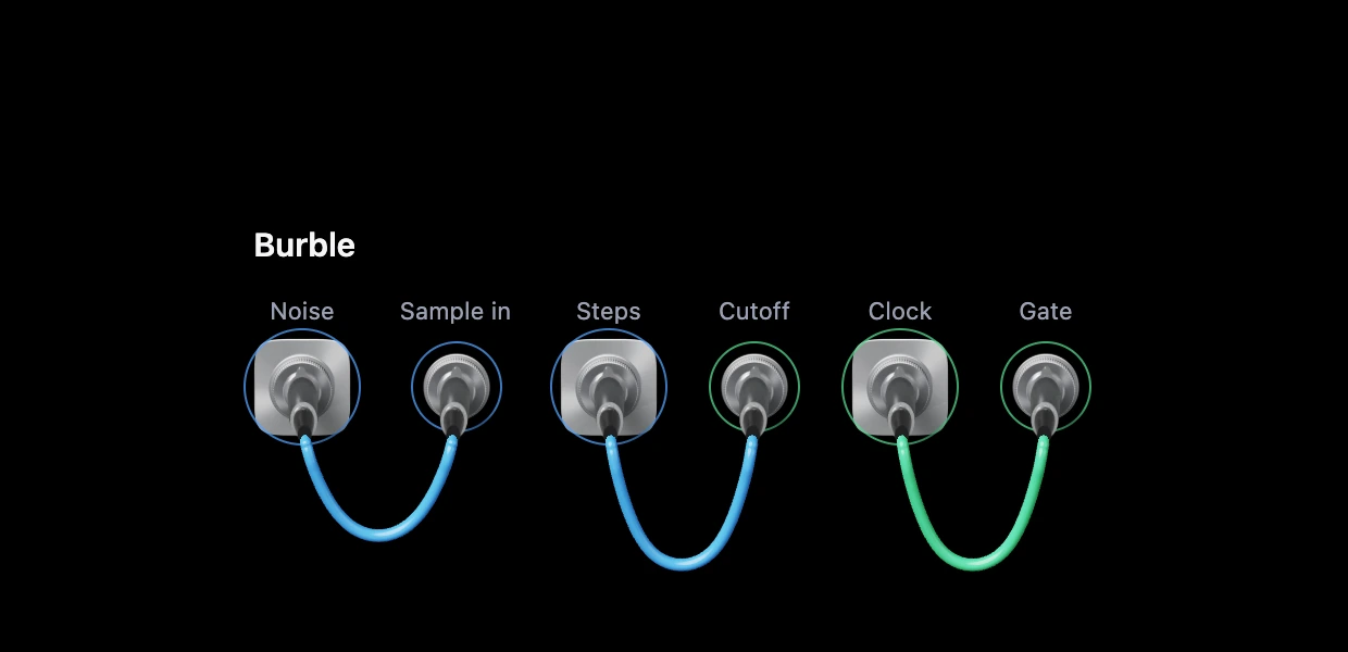
Make it a custom module and give it a face of jacks: the noise's out, the sample and hold's in, its steps, the filter's cutoff, the clock and the gate. Take the wires out, and pull them back as cables, one at a time. With the clock's still out, the switch stays shut and nothing moves. Plug it into the gate and the burble starts.
A cable is an ordinary wire. In the Patch, with Cables on, it's the same wire hanging there, and in the code it's one line: clock -> sh.gate. A jack reaches inside its own module, as a knob does. A wire's 1.0 is 5 V at a jack, so the clock swings ±5 V there.
Try it
- Open Sample and Hold and hold a low key.
- In the parts list, change
C1 hold gnd 100nto1nandRl hold gnd 100Mto1M: a time constant of a millisecond, so each step dies away at once and the burble turns to clicks. - Delete
V1,CpandRp, joingatetogwithRg gate g 100k, and setin gate: from -5 V to 0 V: now it follows the noise for half of every clock. - Wire a Triangle LFO at 0.5 Hz into the circuit's
inin place of the noise: a staircase.
Remember
- A JFET is
J1 drain gate source J111: a switch, on with its gate near its other pins, off about 5 V below them. in gateis a way in of its own: a port in the Patch, a voltage at a point in the parts list. A wire's 1.0 is 5 V there, unless a range says otherwise.- Sampling takes a moment, not half a cycle; an edge through a small capacitor makes that moment.
- Buffers keep the voltage from sagging and let a weak source fill the capacitor.