 SynthMaker
Circuits
The transistor ladder filter
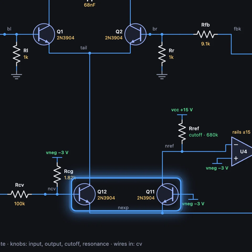
Ten transistors stacked like the rungs of a ladder, a capacitor across each rung, and one current that sets how fast they all follow: a four-pole low-pass that rings when you turn up its resonance. Here it is as a circuit, every part in its parts list.
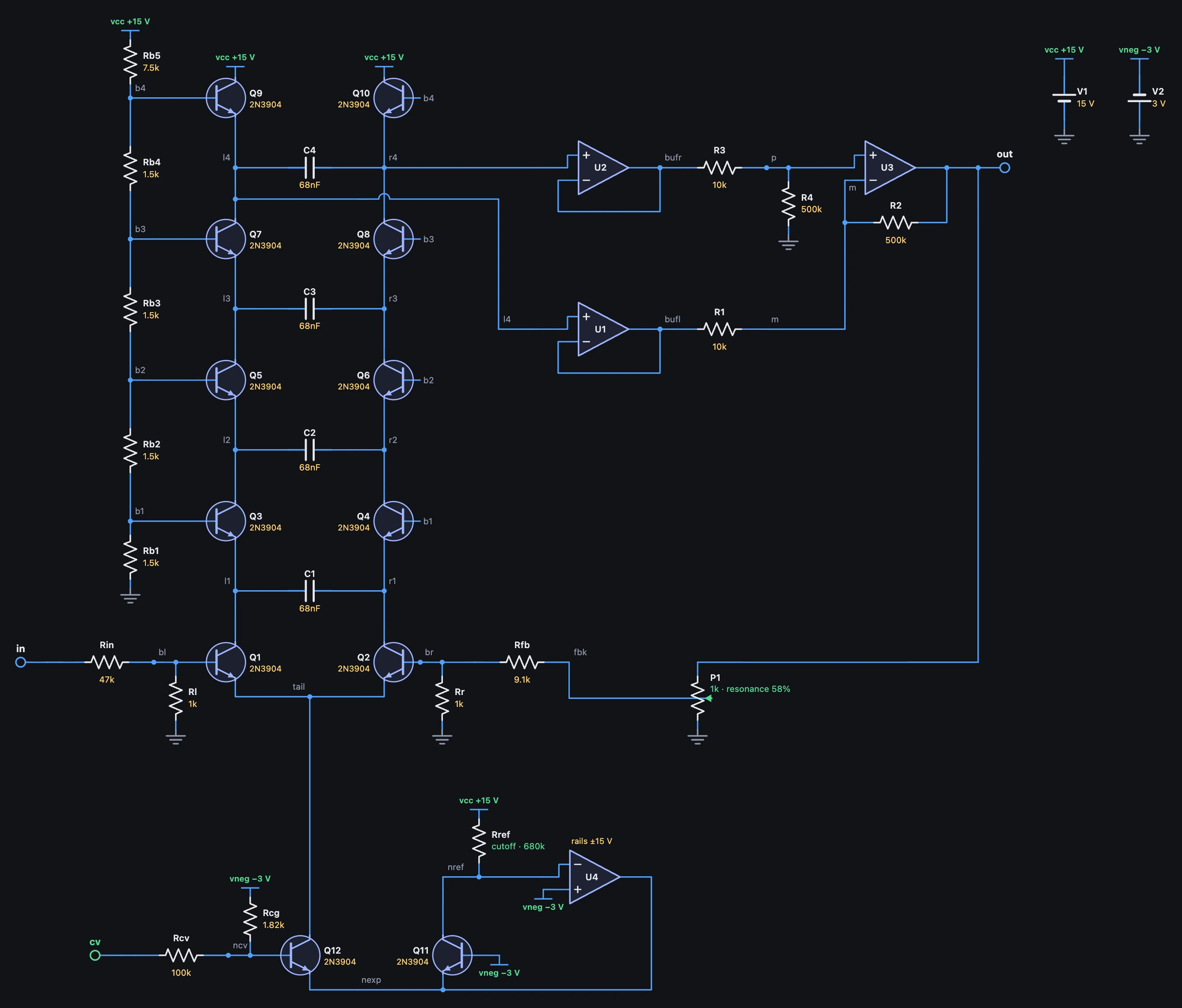
1Part by part
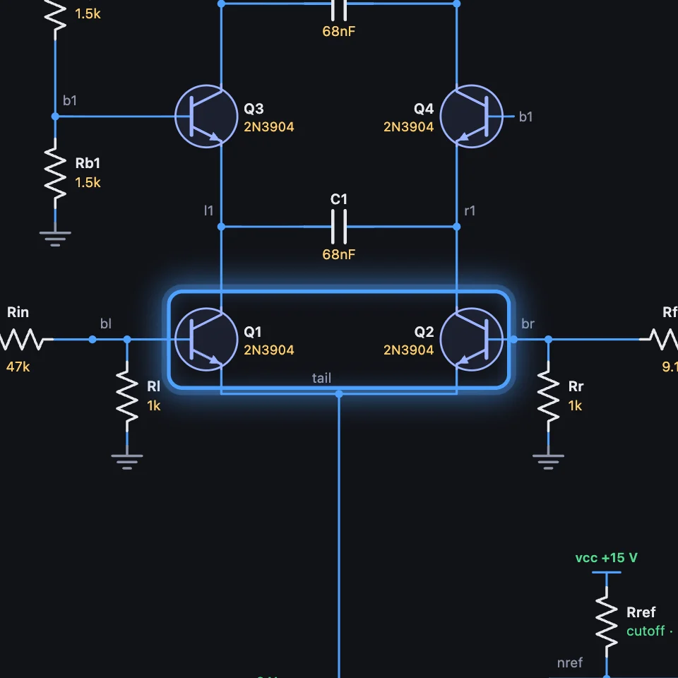
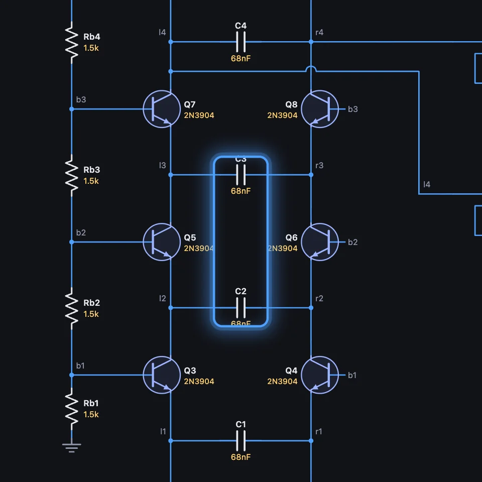
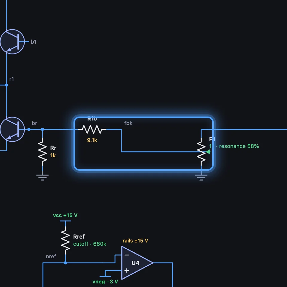
2It plays live
Its transistors are written 2N3904 simple, and it runs at oversample 1x: three voices take about a fifth of a core on a fast computer.
Try it
- Open Ladder Sweep and hold a chord.
- Turn Resonance past 83%: it whistles at its cutoff.
- Turn Cutoff: the whistle follows.
Remember
- The current through the tail is the cutoff: more current, the capacitors follow faster.
- Four capacitors, four poles: 24 dB an octave.
- Ned builds it rung by rung in the lesson A filter from ten transistors (opens in a new tab).