 SynthMaker
OTAs and pots
Two parts that turn a circuit into a synth. A pot is a knob with three legs: a resistor with a wiper you turn along it. An OTA is an amplifier whose gain is a current, so a voltage can set it: an envelope makes it a VCA, a random voltage makes it a filter that never sits still.
New words
A pot (a potentiometer) is a resistor with a third leg, its wiper, that a knob moves along it. Its taper is how: in a straight line, or an audio taper, slow at first.
An OTA (an operational transconductance amplifier) turns the difference between its inputs into a current, as big as the current into its bias pin, Iabc, allows.

1A pot
Write a pot as P, then one end, its wiper, its other end, and its value, the whole of its track. After that its position, and maybe its taper:
setting volume: 70%
P1 a out gnd 100k volume audio
At 100% the wiper is at the first end, at 0% at the last. So this is a volume control: turned up, out is a; turned down, it's ground. Write the end you turn towards first.
A pot's position is a setting in percent, from 0% to 100% unless you give it a range (from 20% to 80%). Its knob turns in a straight line, and a wire's 1 turns it half way along. One setting can turn two pots: a dual pot.
2A tone control
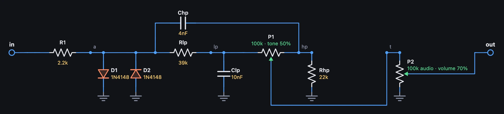
A famous fuzz's tone control is one pot between two filters. From the clipped sound, a low-pass (Rlp, Clp) and a high-pass (Chp, Rhp) run side by side; the pot's wiper picks how much of each. All bass at 0%, all treble at 100%, and half way, a dip in the middle frequencies, the sound that made it famous. After it, a volume pot on the audio taper.
Rlp a lp 39k
Clp lp gnd 10n
Chp a hp 4n
Rhp hp gnd 22k
P1 hp t lp 100k tone
P2 t out gnd 100k volume audio
In Scooped Tone an LFO is wired into tone, so the pot turns slowly back and forth on its own.
3An OTA
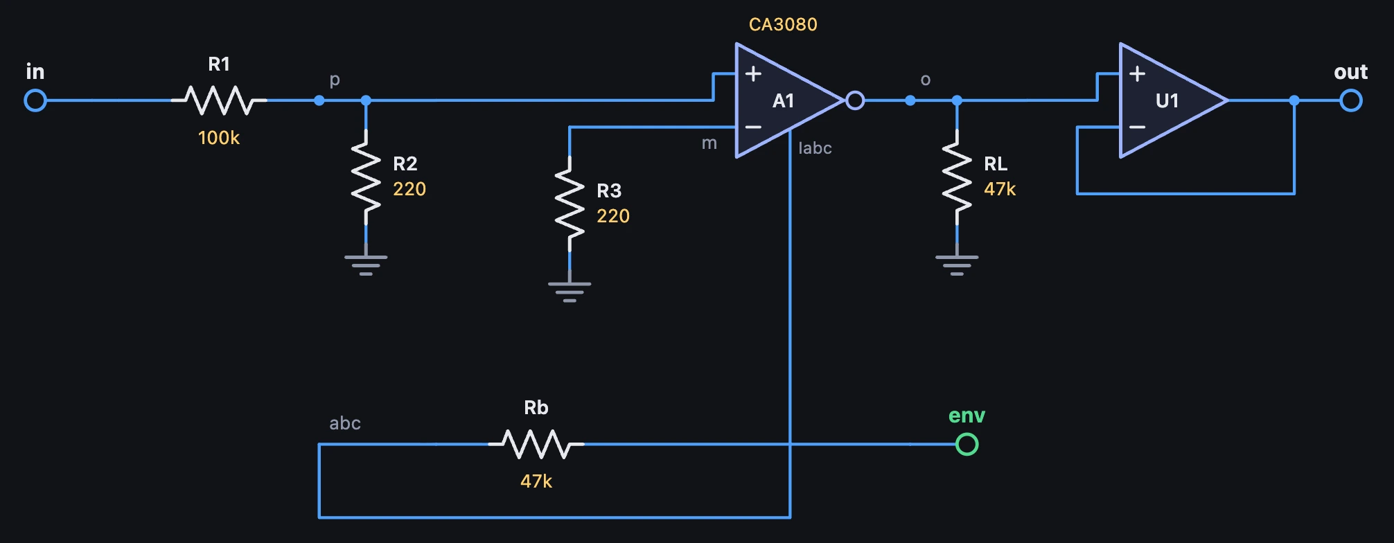
An op-amp's out is a voltage. An OTA's is a current: the difference between its inputs, times its transconductance, and that is set by another current, the one into its bias pin. Write it as A, then its + input, its − input, its out, its bias pin and its model:
A1 p m o abc CA3080
Rb env abc 47k
RL o gnd 47k
The bias pin is a junction down to ground, so feed it as a real OTA is fed, through a resistor from a control voltage: Rb turns 10 V into about 0.2 mA. Its out is a current, so give it a load (RL) to make a voltage from it.
Its current is Iabc tanh((v+ − v−) / 2 Vt), two transistors' law: a straight line for a few millivolts, then it bends and stops at Iabc. So the sound goes in through a divider (100k and 220 Ω make 6 V into 13 mV), and driven harder, it rounds off softly.
4An OTA as a VCA
Wire an Envelope into a named input, in env: from 0 V to 10 V, and through Rb it sets Iabc: how loud the note is, the way synths of the seventies did it with a CA3080. U1 buffers the out. Turn input up and the OTA's tanh starts to round the peaks. Ned builds one, then pushes it until it growls, in the lesson An amp from one OTA, pushed until it growls (opens in a new tab).
# An OTA as a VCA, the way synths of the seventies used a CA3080. Its out is a current, Iabc tanh((v+ - v-) / 2 Vt): how# loud the sound comes out is how much current flows into its bias pin. The Envelope's 1 is 10 V at env, and Rb turns that# into up to about 0.2 mA. R1 and R2 bring the sound down to a few millivolts at the + input (an OTA's inputs only stay in a# straight line for a few tens of millivolts; drive them harder with input and tanh rounds the peaks off), R3 gives the - input# the same 220 ohms to ground, RL turns the current back into a voltage, and U1 buffers it. Under about 0.6 V at the bias pin# its junction lets almost nothing through, so the tail of each note falls away a little faster than the Envelope does.circuit OtaVca setting input: 4 V, from 0.4 V to 20 V setting output: 11 V, from 1.1 V to 55 V in env: from 0 V to 10 V R1 in p 100k R2 p gnd 220 R3 m gnd 220 Rb env abc 47k A1 p m o abc CA3080 RL o gnd 47k U1 o out out opampend5Two OTAs make a filter
Into a capacitor, an OTA's current makes an integrator: its voltage follows the input, as fast as Iabc lets it. Two in a row, each with a buffer after it (U3, the band-pass; U4, the low-pass and out), and the low-pass fed back into the first one's − input, make a 12 dB low-pass whose cutoff is a current. Rq feeds the band-pass back too: the bigger it is, the more it rings (Q is Rq over 100k).
The cutoff is the current into both bias pins, from the 15 V supply through Rk1 and Rk2. One cutoff setting turns them both, a dual pot: from 1M (about 100 Hz) down to 33k (2.9 kHz). With its range made wider and an Envelope on its cutoff, it plays an acid line (opens in a new tab).
6A random filter
Wire Circuits 3's sample and hold, a circuit of its own, into cutoff: sh -> rf.cutoff. A wire turns a setting from where it's set, half its travel for a 1, so each held voltage of the noise turns the dual pot to a new place, a new random cutoff on every clock: the burble, from a filter whose every part you can see. Ned builds it, chip by chip, in the lesson A filter from two OTA chips (opens in a new tab).
# A two-OTA low-pass whose cutoff a sample and hold sets. Two CA3080s, each an integrator into a 1n capacitor (Ca, Cb) with a# buffer after it: U3 the band-pass, U4 the low-pass, out. A1's - input sums the low-pass and the band-pass (Rq): the bigger# Rq, the less the band-pass damps it and the more it rings (Q = Rq / 100k). How fast the integrators run is the current into# their bias pins, from the 15 V supply through Rk1 and Rk2: cutoff turns them together, a dual pot, from 1M (about 100 Hz)# down to 33k (2.9 kHz). The sample and hold's wire into cutoff turns it from where it's set, up to half its travel either way.circuit RandomFilter setting input: 6 V, from 0.6 V to 30 V setting output: 7 V, from 0.7 V to 35 V setting cutoff: 150k, from 1M to 33k setting resonance: 220k, from 47k to 680k V1 vcc gnd 15V R1 in p1 100k R2 p1 gnd 220 A1 p1 m1 c1 abc1 CA3080 Rlp out m1 100k Rq bp m1 resonance R4 m1 gnd 220 Ca c1 gnd 1n U3 c1 bp bp opamp R5 bp p2 100k R6 p2 gnd 220 A2 p2 gnd c2 abc2 CA3080 Cb c2 gnd 1n U4 c2 out out opamp Rk1 vcc abc1 cutoff Rk2 vcc abc2 cutoffend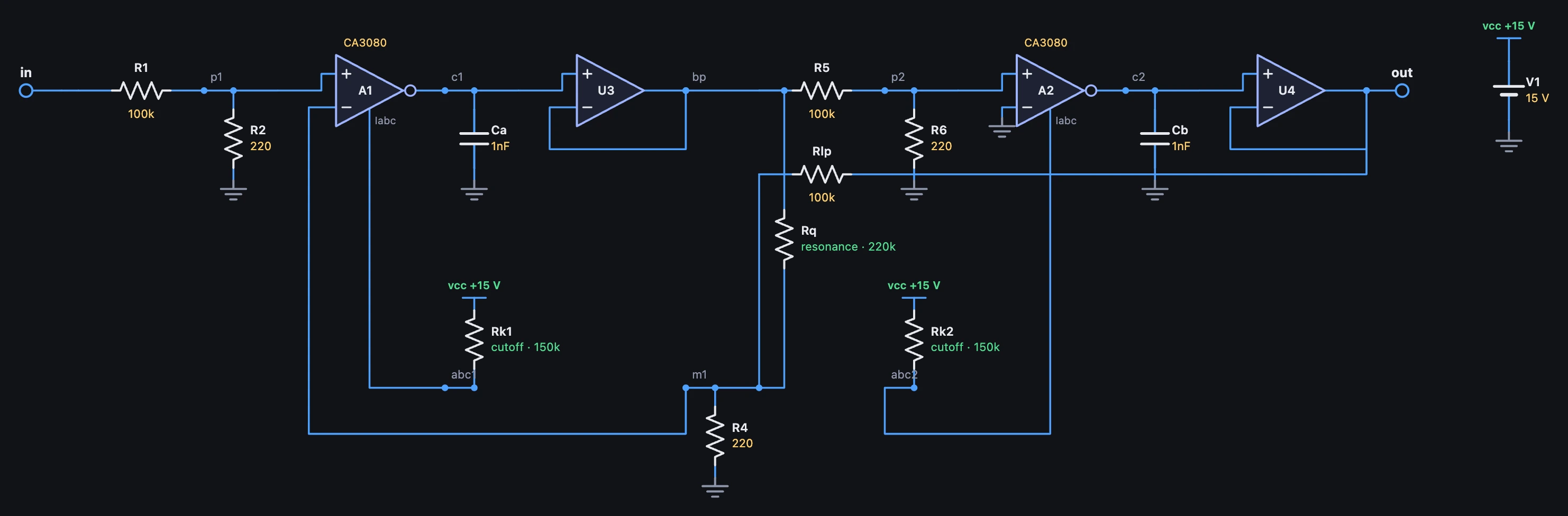
Try it
- Open Scooped Tone and turn tone by hand, then pull the LFO's wire out: the knob alone sets the pot.
- In OTA VCA, turn input to 12 V and listen to the OTA round off the loudest notes.
- In Random Filter, turn cutoff down: the random places move with it, lower and darker.
- Turn resonance up to 680k: each jump of the cutoff rings.
Remember
- A pot is
P1 a wiper b 100k position taper: 100% puts the wiper ata, 0% atb; its position is a setting in percent, turning in a straight line. - An OTA is
A1 plus minus out bias CA3080: its out is a current,Iabc tanh((v+ − v−) / 2 Vt). - Feed the bias pin through a resistor from a control voltage, give the out a load, and keep its inputs to a few millivolts.
- A current into a capacitor is an integrator; two OTAs and two buffers are a filter whose cutoff a voltage sets.