 SynthMaker
Circuits
Circuits for audio: hear how they work
How the circuits inside guitar pedals and synthesizers really work, one page at a time. Every page answers one question in plain words, with the numbers worked out, and lets you play the circuit right there: turn its knobs, switch its versions and watch the Scope.
Each circuit is simulated part by part, the same way SynthMaker plays every circuit, and checked against ngspice, a standard circuit simulator. New pages are added as they're written; the newest are listed first.
New to electronics? Start with How a voltage divider works, then follow the chapters in order. Already know your way around? Jump to any page; each one stands on its own.
Start hereHow a voltage divider worksRecently added
1Parts and signals
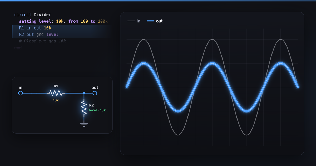 How a voltage divider worksA voltage divider is two resistors in a row, and the output, taken from between them, is the input times R2 / (R1 + R2).
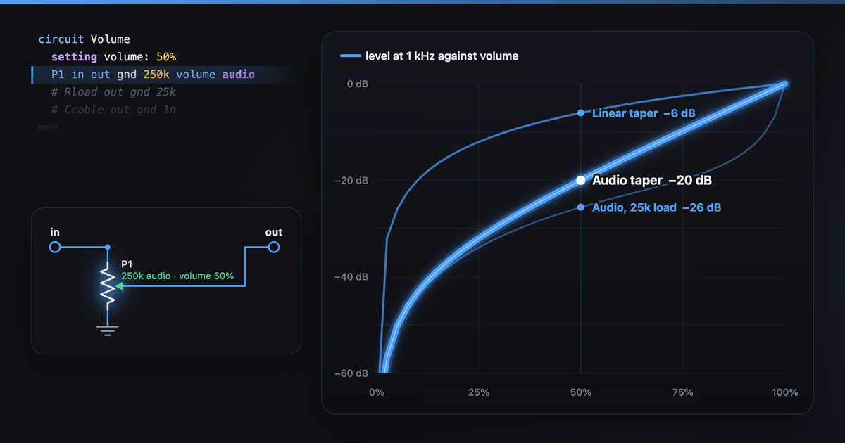 Volume pot taper: linear vs log, and why loading mattersA volume pot is a voltage divider; its taper is how the output follows the knob.
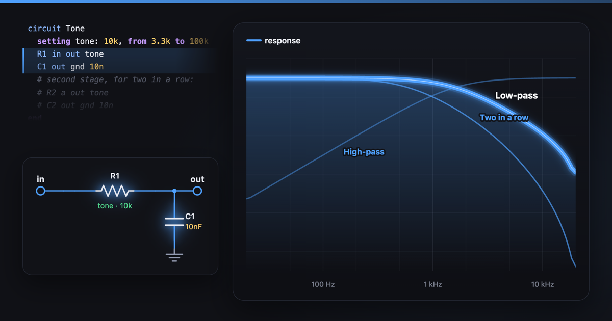 How an RC filter works: capacitors and a tone controlAn RC filter is a resistor and a capacitor; as a low-pass it keeps notes below its corner, f = 1/(2πRC), and turns everything above down 6 dB per octave: 10 kΩ and 10 nF give 1.59 kHz.
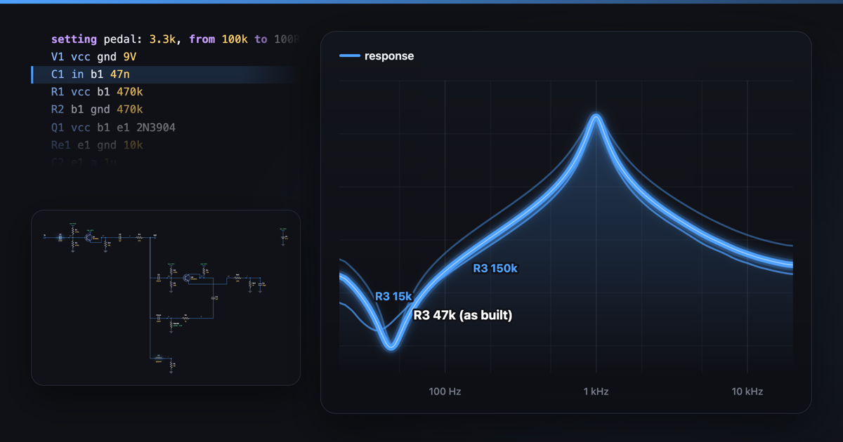 How a wah pedal works: coils and resonanceA wah pedal is a coil and a capacitor that ring together at one frequency, boosting a narrow band.
2Diodes and clipping
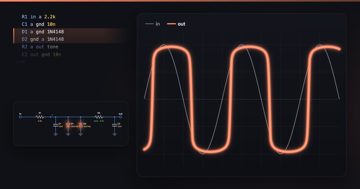 How a diode clipper worksA diode clipper is a resistor into two diodes facing opposite ways.
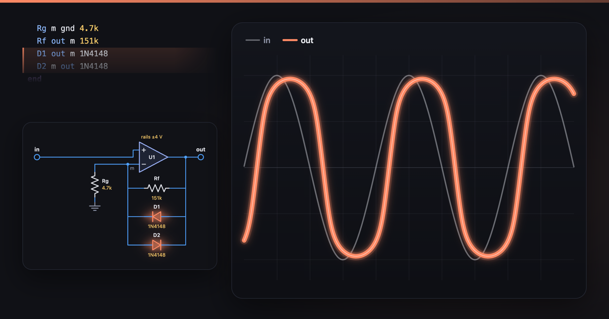 Hard and soft clippingHard clipping cuts a wave off at a flat ceiling with a sharp corner, like an op-amp hitting its ±4 V rails; soft clipping bends it through a gradual knee, like diodes in its feedback.
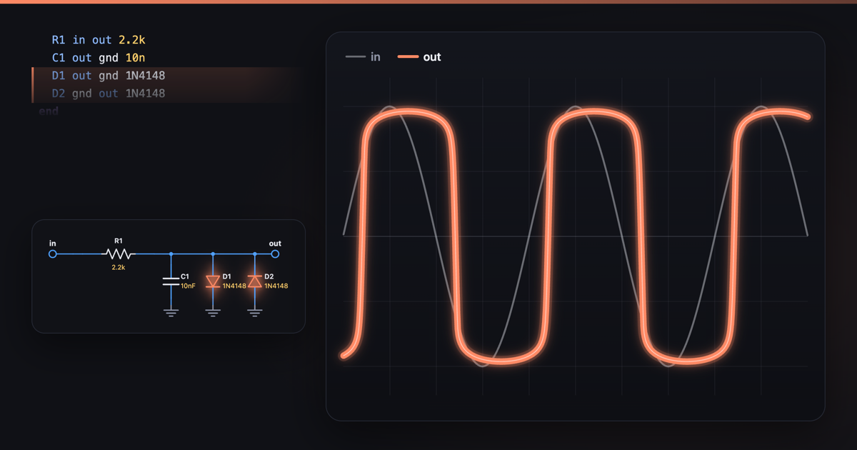 Silicon, germanium and LED clipping diodesA clipping diode's material sets where it clips: in this circuit, with 6 V in, silicon (1N4148) holds the peaks at 0.63 V, germanium (1N34A) at 0.34 V and a red LED at 1.63 V.
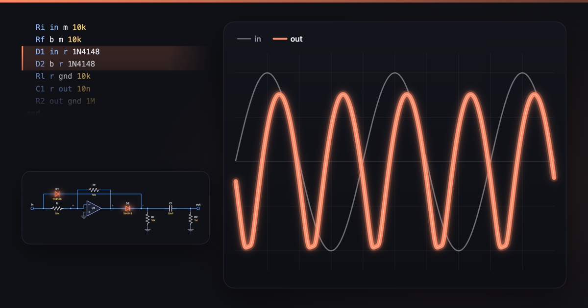 How an octave-up pedal works: rectifiersAn octave-up pedal flips the bottom half of the wave up, a full-wave rectifier, so each cycle of the note becomes two: a 110 Hz note comes out at 220 Hz.
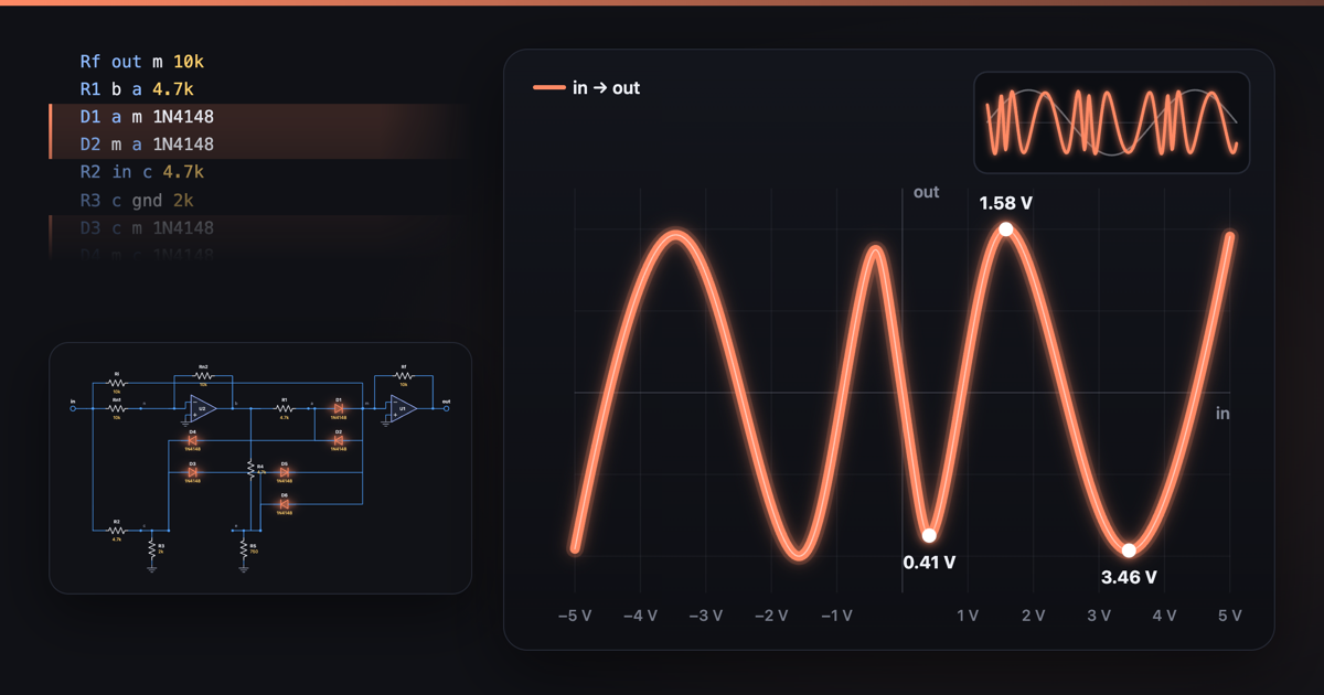 How a wavefolder works: folding with diodesA wavefolder turns a wave back on itself once it passes a threshold, instead of flattening it like a clipper.
3Op-amps
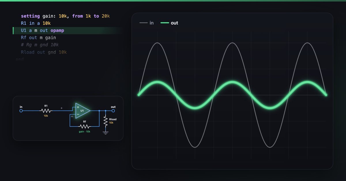 The op-amp's two rules: buffer, gain and a mixerAn op-amp follows two rules: it drives its output until its two inputs are at the same voltage, and no current flows into those inputs.
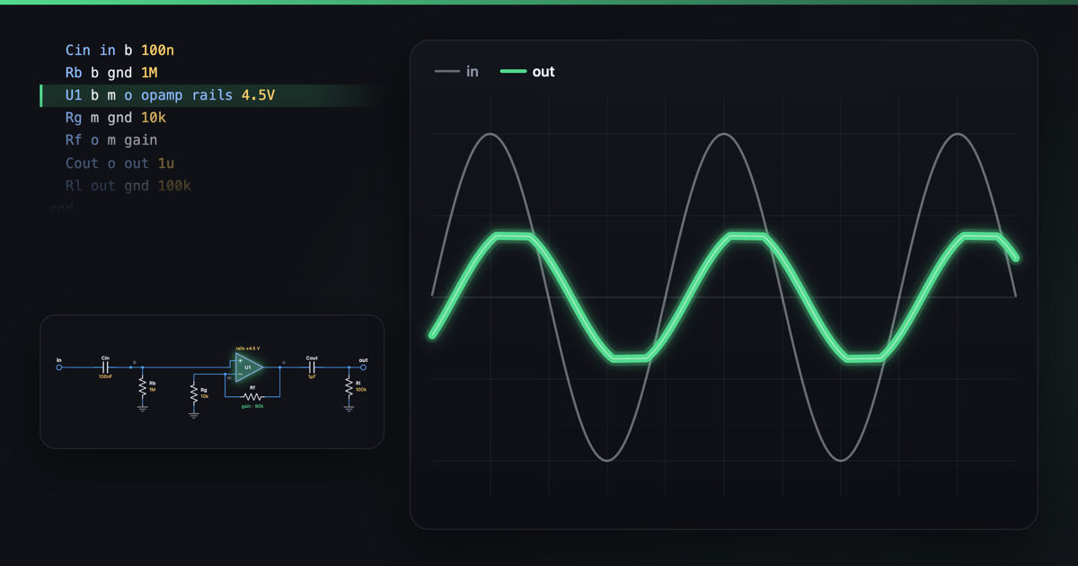 Op-amp rails and headroom: why it clipsAn op-amp's output can't swing past its supply rails, so running a pedal at 18 V instead of 9 V doubles its swing, from ±4.5 V to ±9 V: 6 dB more headroom before it clips.
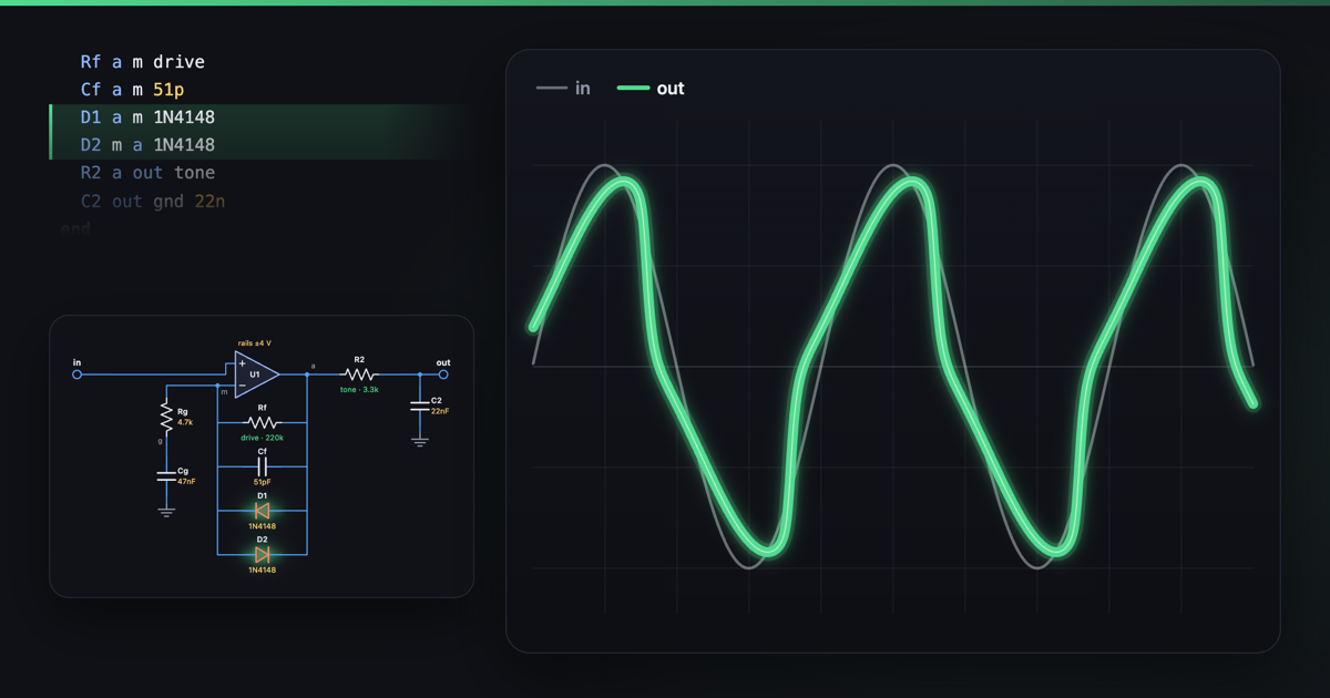 How op-amp overdrive works: diodes in the feedback loopAn op-amp overdrive is a gain stage with two diodes across its feedback resistor.
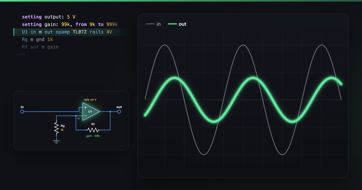 Slew rate and bandwidth: why real op-amps sound differentReal op-amps sound different mostly through bandwidth, not slew rate.
4Filters
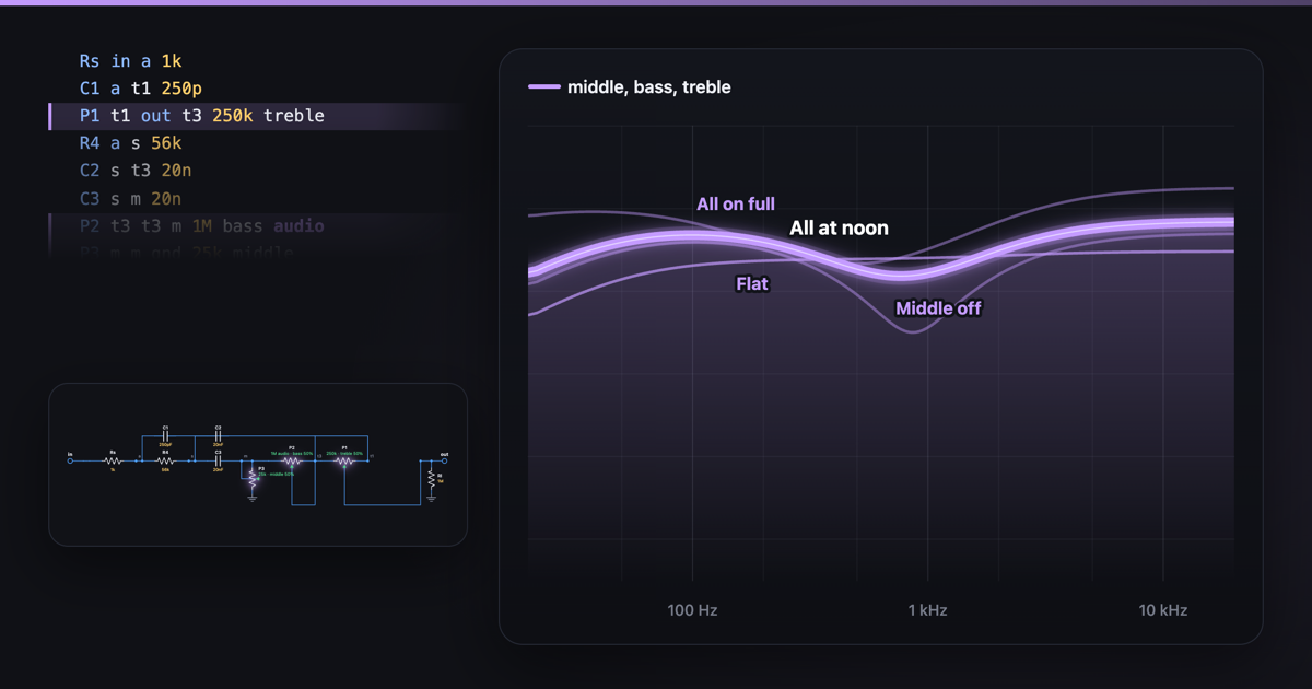 How a tone stack works: passive bass, middle and trebleA tone stack is three pots, three capacitors and a resistor that share out an amp's signal by frequency.
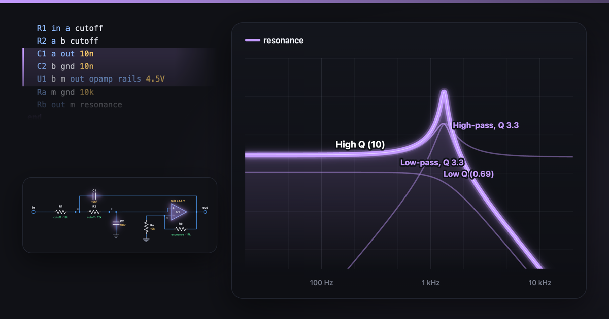 How a Sallen-Key filter worksA Sallen-Key filter is two resistors, two capacitors and one op-amp: a low-pass falling 12 dB per octave above f = 1/(2π√(R1R2C1C2)).
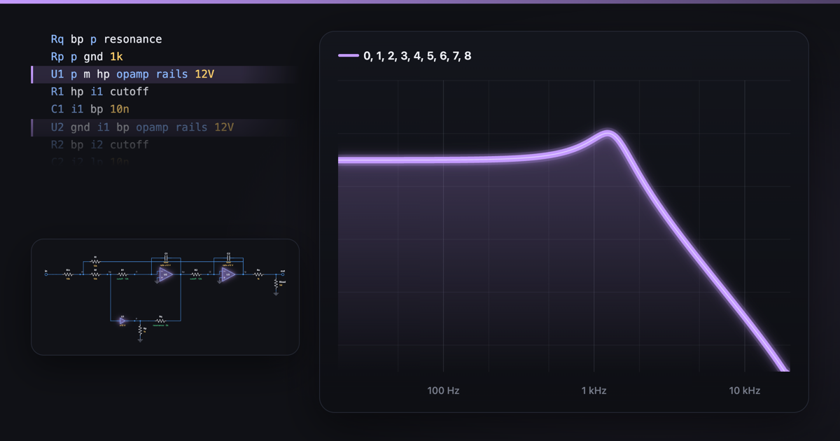 How a state-variable filter worksA state-variable filter is two integrators and a summing op-amp in a loop: one circuit gives low-pass, band-pass and high-pass at once, and low plus high makes a notch.
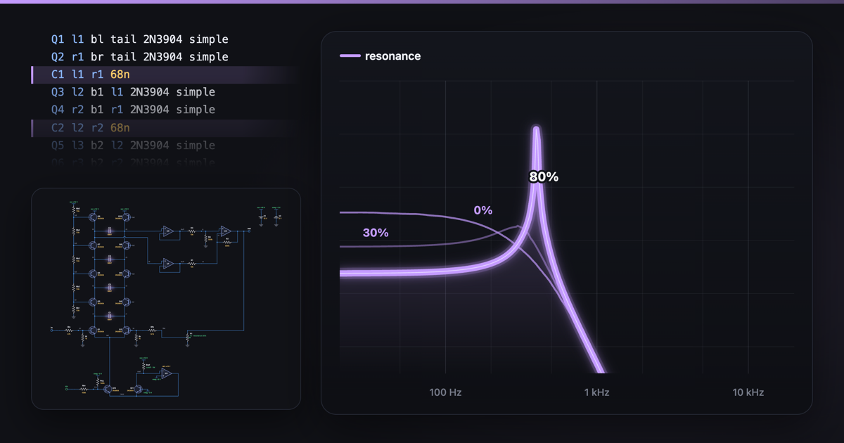 How a transistor ladder filter worksA transistor ladder filter is four stacked pairs of transistors, each with a capacitor across it, all sharing one current that sets the cutoff: four poles, 24 dB per octave.
5Transistors and valves
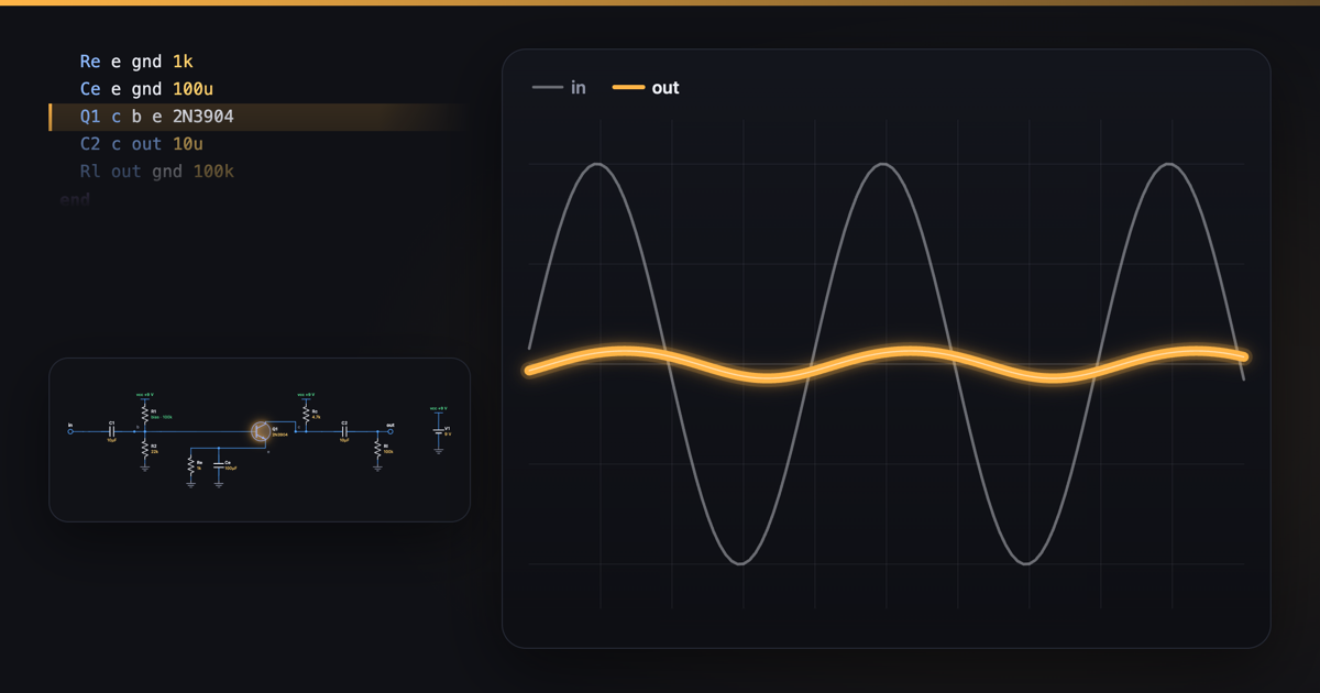 How a transistor amplifies: biasing a common-emitter stageA transistor amplifies because its collector current follows its base voltage: ten times the current for every 60 mV more.
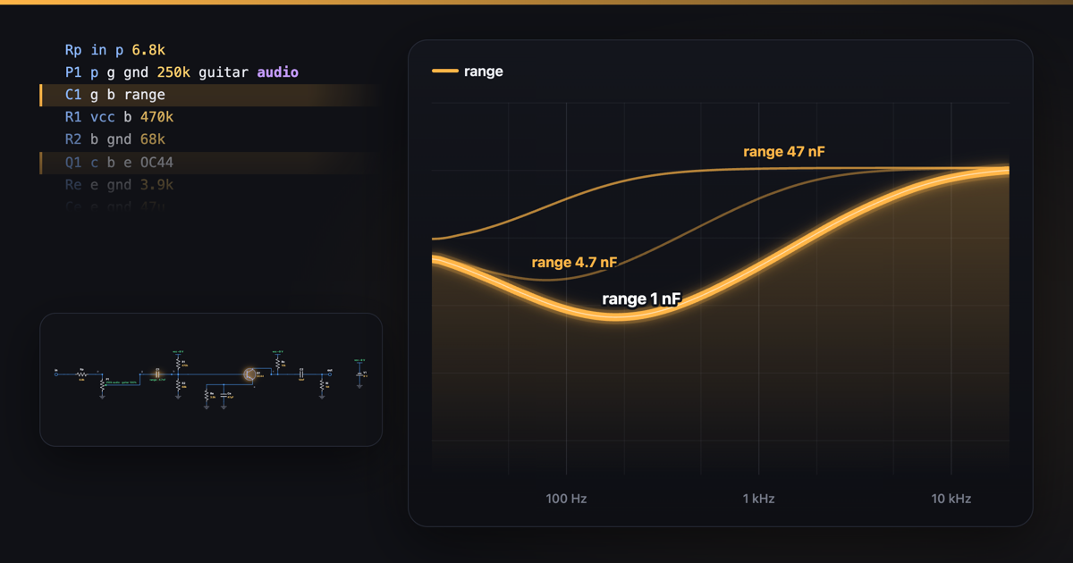 How a treble booster worksA treble booster is one germanium transistor amplifying about 75 times, fed through a small capacitor that passes mostly the highs: 5 kHz comes out 34 dB louder, 100 Hz only 10 dB.
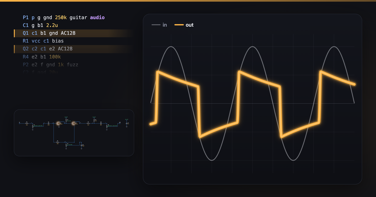 How a fuzz pedal works: two germanium transistorsA classic fuzz is two germanium transistors in a feedback pair amplifying about 1,000 times, so a 0.1 V guitar note, 25 times what it passes cleanly, hits their limits and comes out square.
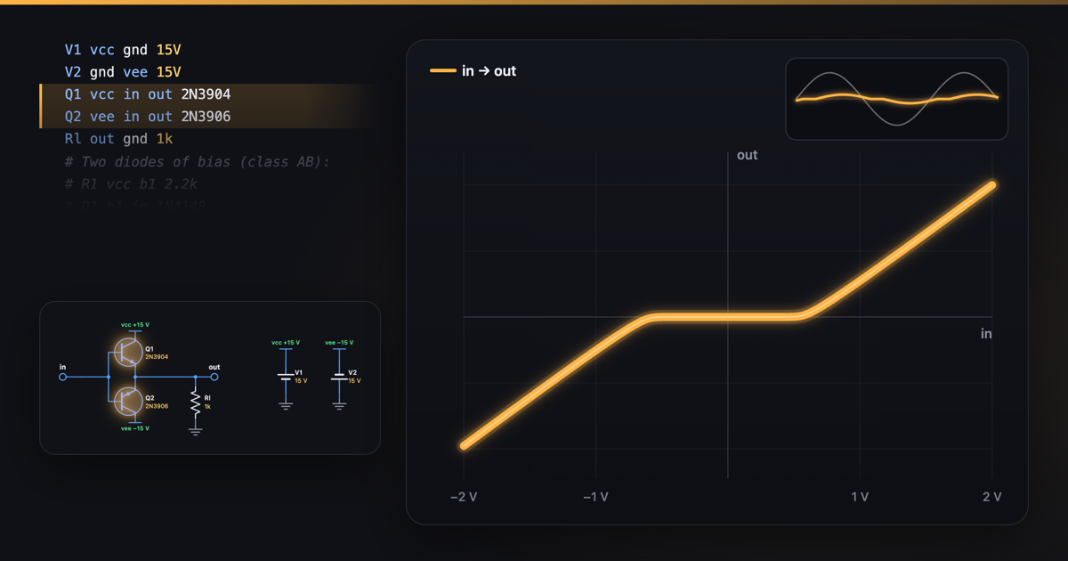 Crossover distortion: why a push-pull stage needs biasCrossover distortion is the gap a push-pull output leaves around zero: its NPN and PNP transistors each need about 0.6 V before they conduct, so the middle 1.2 V of the wave is lost, worst on quiet sounds.
6Oscillators
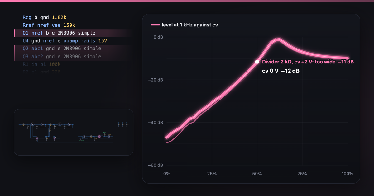 One volt per octave: how an exponential converter works
7Voltage control
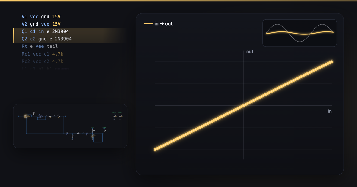 How a differential pair works: where tanh comes fromA differential pair is two transistors sharing one tail current, which splits between them by the voltage difference at their bases as tanh(ΔV / 51.7 mV).
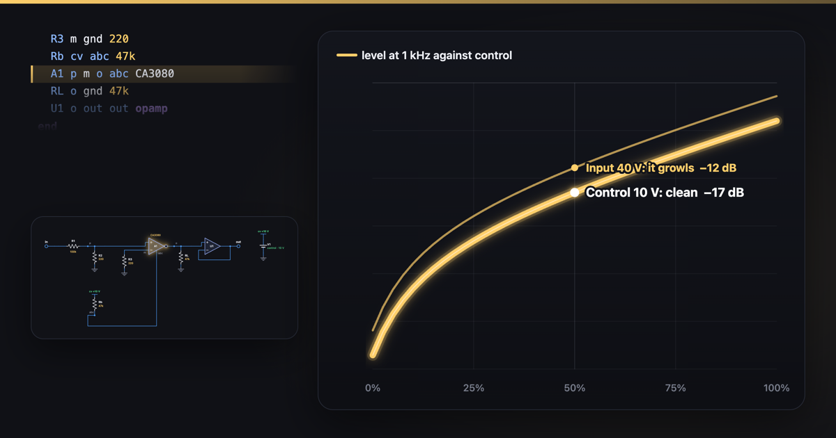 How a VCA works: an OTA turns the volume with a currentAn OTA's output current is its input voltage times a gain set by the current into its bias pin, 19 × Iabc.
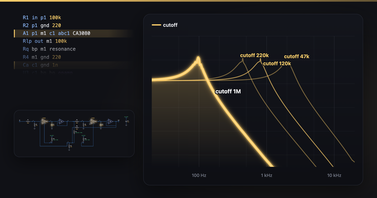 How an OTA filter works: two integrators and a currentAn OTA filter is two OTAs, each charging a capacitor, in a loop: a 12 dB per octave low-pass whose cutoff follows the OTAs' bias current, 6.75 Hz per µA here, so 120 µA gives 810 Hz.
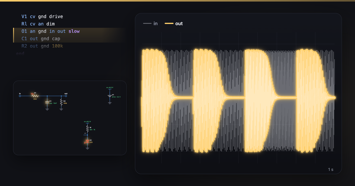 How a low-pass gate works: a light-dependent resistorA low-pass gate is a filter and a VCA in one: an LED lights a light-dependent resistor in an RC low-pass.
8Envelopes, LFOs and sample and hold
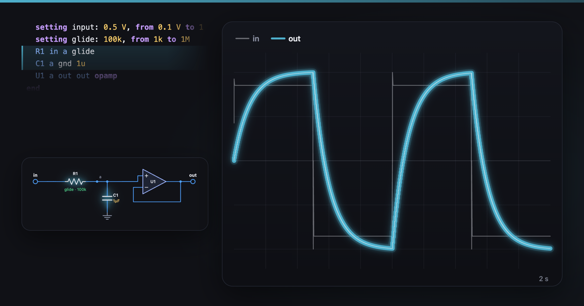 How portamento works: a slew limiterA slew limiter makes a stepped pitch voltage glide: a resistor fills a capacitor, and an op-amp buffer copies it.
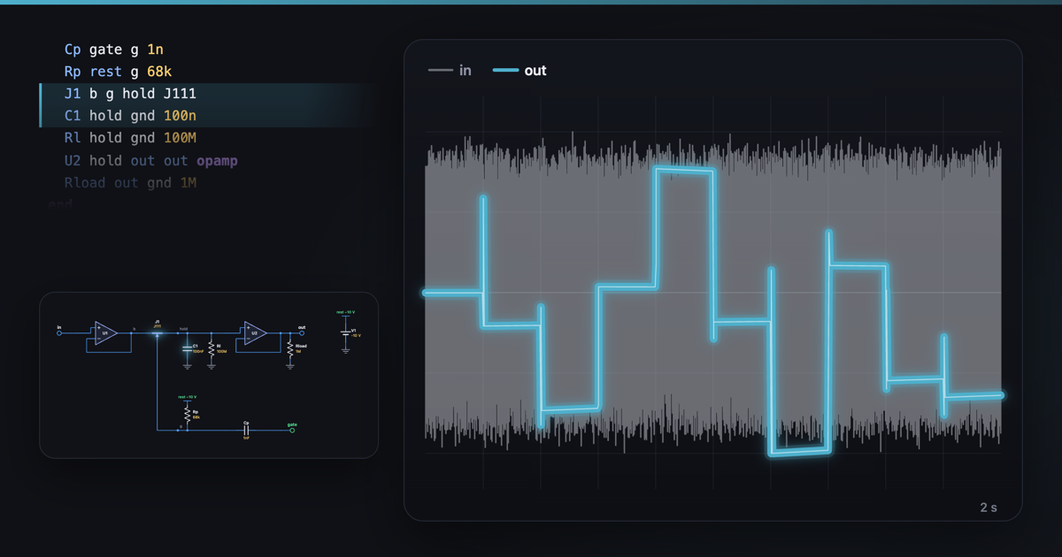 How sample and hold works: a capacitor remembersA sample and hold turns a switch on for about 50 µs each clock tick, so a capacitor charges to the input's voltage and holds it until the next tick.
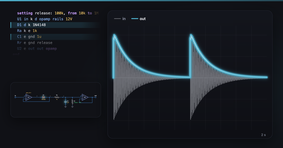 How an envelope follower worksAn envelope follower turns a sound into a voltage that follows how loud it is: a diode rectifies it and a capacitor smooths it.
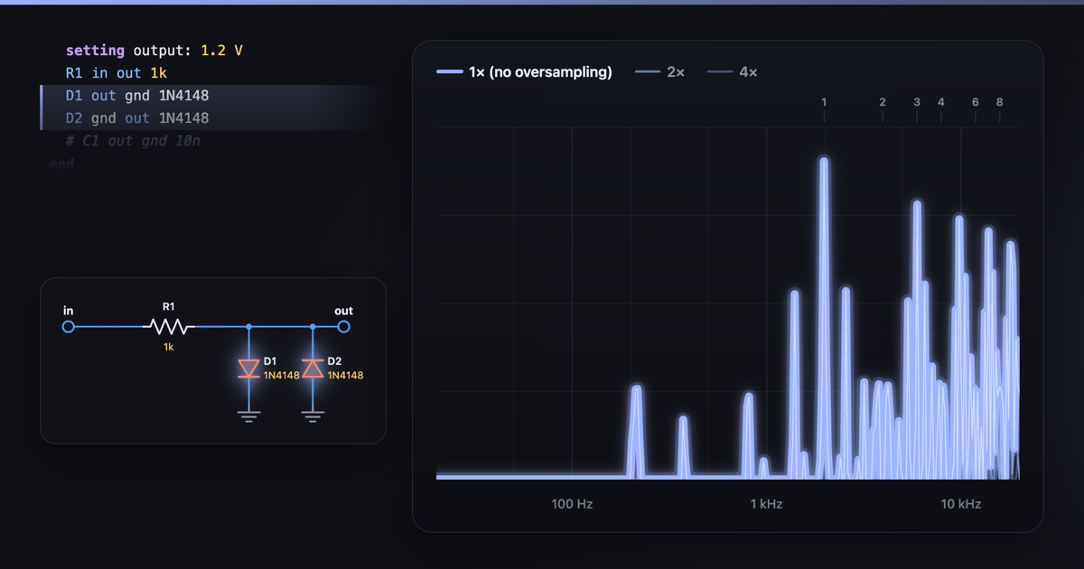 How a circuit simulator hears a circuit