 SynthMaker
The TR-808 Cymbal: a Physically-Informed, Circuit-Bendable, Digital Model
Read the paperdoi:10.5281/zenodo.850891
A classic drum machine makes its cymbal from six square waves at clashing pitches, from 205 Hz to 800 Hz: two band-pass filters keep only their overtones around 3.4 kHz and 7.1 kHz, and three short envelopes, clipping amplifiers and high-pass filters turn that buzz into a crash that dies away.
Abstract
We present an analysis of the cymbal voice circuit from a classic analog drum machine […]. A digital model based on this analysis […] retains the salient features of the original. Developing physical models of the device’s many sub-circuits allows for accurate emulation of circuit-bent modifications (including component substitution, changes to the device’s architecture, and voltage starve)—complicated behavior that is impossible to capture through black-box modeling or structured sampling. This analysis will support circuit-based musicological inquiry into the history of analog drum machines and the design of further mods.
The paper’s abstract, as published under CC BY 3.0.
Read along
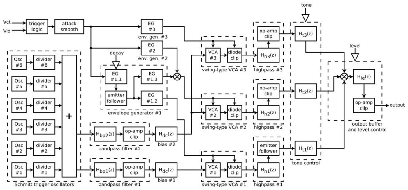
Each step quotes the paper, says what it means in plain words, and gives you the circuit to play. The paper is open access under CC BY 3.0, so its words and figures appear as published. Its Figure 1, the full schematic, isn't shown: it is adapted from the drum machine's service notes. Instead, each step gives our own parts list, drawn by SynthMaker, with the original circuit's component values.
- Step 1 · One square-wave oscillator (§3, equations 1–2)
- Step 2 · The duty cycle doesn't depend on R or C (§3, equation 3)
- Step 3 · Six oscillators, summed (§3, Figure 3)
- Step 4 · Two band-pass filters (§4, equation 5, Figure 4)
- Step 5 · Every edge rings the filter (§4, Figure 5)
- Step 6 · The trigger and the accent (§5)
- Step 7 · The attack smoother (§6, equation 6, Figure 6)
- Step 8 · The envelope generators (§7, Figure 7)
- Step 9 · The swing-type amplifier (§8, Figure 8)
- Step 10 · Three high-pass filters (§9, Figure 4)
- Step 11 · The tone stage (§10, Figure 9)
- Step 12 · The output buffer and level (§11, Figure 10)
- Step 13 · Making it digital (§12)
- Step 14 · The whole voice (§13, Figure 11)
- Step 15 · Circuit bends (§12–13, Figure 11)
Step 1 · One square-wave oscillator (§3, equations 1–2)
The paper says
"In each of these astable multivibrators, the Schmitt trigger inverter acts as the bistable element, and a passive network of a single resistor and capacitor provides an RC time constant that tunes the oscillator to a particular frequency." (§3)
"Since the positive-going and negative-going threshold voltages for a Schmitt trigger input are different, the circuit will oscillate back and forth as the capacitor is alternatively charged and discharged." (§3)
In plain words
The cymbal starts with the simplest oscillator there is: one logic gate, one resistor and one capacitor. The gate is a Schmitt-trigger inverter. Its output is either low, 0 V, or high, 5 V, and it is the opposite of its input. The trick is that it switches at two different input levels. A rising input has to pass 2.7 V before the output drops low. A falling input has to go below 2.1 V before the output jumps high again. That gap is called hysteresis.
Now wire the resistor from the output back to the input, and the capacitor from the input to ground. With the output high, the capacitor charges through the resistor. At 2.7 V the output flips low, and the capacitor starts to discharge. At 2.1 V the output flips high, and it charges again. Round and round: a square wave. Equations 1 and 2 give the time each half takes from R, C and those four voltages. Oscillator 1 has 560 kΩ and 18 nF, which makes 205.3 Hz, just under G♯3.
The paper doesn't print the two thresholds; they come from the chip's data sheet. But 2.7 V and 2.1 V are what its numbers imply: put them into equations 1 to 3 with each oscillator's R and C, and out come the paper's frequencies and duty cycle.
SynthMaker has no Schmitt-trigger gate as a part, so a comparator stands in. A divider from a 5 V supply and from the comparator's own output sets its two switching points at the same 2.7 V and 2.1 V, and its output swings between the same 0 V and 5 V. Same thresholds, same output levels, so by equations 1 to 3, the same pitch and duty. Where the two would part company is when the supply voltage changes. That comes in step 15.
Try it
circuit Schmitt1 setting output: 6.5 V, from 1 V to 10 V V1 v5 gnd 5V Rin in gnd 100k # in isn't used: the oscillator runs on its own U1 p c o comparator rails 0V 5V R40 o c 560k C1 c gnd 18n Rh o p 100k Rx v5 p 28.571k Ry p gnd 26.087k Cout o out 1u Rout out gnd 100kendPress Play to see the wave after the circuit, at out.
U1 is the comparator: its output is high while its + input (p) is above its − input (c). Rh, Rx and Ry set its two switching points. R40 and C1 are the timing pair, named as in the original. Cout and Rout keep the wave's 2.4 V average off the output, so you hear it centred. Watch the Scope: a square wave, a little under half its time high. Open it in SynthMaker and change C1 or R40: the pitch moves.
Step 2 · The duty cycle doesn't depend on R or C (§3, equation 3)
The paper says
"Plugging in Equations (1)–(2) to the definition of duty cycle, the time constant RC drops out—the duty cycle depends only on the inverter’s device properties VT−, VT+, VOL, and VOH" (§3)
In plain words
The duty cycle is the share of each cycle the wave spends high. Both halves of the cycle scale with RC, so when you divide one by the total, RC cancels. Change the resistor or the capacitor and the pitch moves, but the shape stays. Only the four voltages decide the shape.
With a 5 V supply, the paper gets 47.98%: a hair under half. The reason is that the two thresholds, 2.1 V and 2.7 V, sit a little below the middle of 0 to 5 V. Charging up towards 5 V, the capacitor has more voltage pushing it than when discharging towards 0 V, so the high half is the shorter one. That small lopsidedness matters for the sound. A square wave at exactly 50% has only odd harmonics. At 47.98%, a 2nd harmonic appears too, about 24 dB below the fundamental.
Try it
circuit Schmitt1 setting output: 6.5 V, from 1 V to 10 V V1 v5 gnd 5V Rin in gnd 100k # in isn't used: the oscillator runs on its own U1 p c o comparator rails 0V 5V R40 o c 560k C1 c gnd 18n Rh o p 100k Rx v5 p 28.571k Ry p gnd 26.087k Cout o out 1u Rout out gnd 100kendPress Play to see the wave after the circuit, at out.
"Half the capacitor" plays an octave up, 410.7 Hz, and on the Scope the wave keeps exactly the same shape. "Thresholds moved up" shifts both switching points to 3.0 V and 3.6 V. Now the capacitor charges slowly and discharges fast, so the wave spends 66% of its time high, and the pitch drops to 184 Hz with no change to R or C.
Step 3 · Six oscillators, summed (§3, Figure 3)
The paper says
"The six oscillators have nominal frequencies (or ranges) of 205.3, 369.6, 304.4, 522.7, 359.4–1149.9, and 254.3–627.2 Hz." (§3)
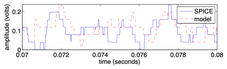
"All six oscillators are summed via voltage dividers in a passive mixing network." (§3)
In plain words
The drum machine has six of these oscillators, all on one chip, and several of its voices share them. Four have fixed pitches: 205.3, 369.6, 304.4 and 522.7 Hz. The last two have trimmers inside the case, set at the factory to 800 Hz and 540 Hz. Here they're written as single resistors at those settings.
A square wave is a stack of odd harmonics. Six of them, below 20 kHz, make about 160 partials, and they don't line up the way a chord's do. That scattered spectrum is what makes the sound metallic, and it's the raw material of the cymbal.
Each oscillator feeds a 120 kΩ resistor into one node, with 1 kΩ to ground. So each one adds about 40 mV to the node when it's high, and all six together reach 0.24 V: the stepped wave in Figure 3.
One SynthMaker circuit holds at most four comparators, so the six oscillators play as two circuits. OscBankA holds oscillators 1 to 3 and passes on the average of their three outputs. OscBankB feeds that average through 40 kΩ, which is what three 120 kΩ resistors in parallel look like from the node. By Thévenin's theorem, that is exactly the same as joining all six at one node. OscBankB also carries the two band-pass filters' inputs from step 4, so the node sees the same load as in the full circuit.
Try it
circuit OscBankA setting output: 5 V V1 v5 gnd 5V Rin in gnd 100k # in isn't used: the oscillators run on their own # oscillator 1: 205.3 Hz U1 p1 c1 o1 comparator rails 0V 5V R40 o1 c1 560k C1 c1 gnd 18n Rh1 o1 p1 100k Rx1 v5 p1 28.571k Ry1 p1 gnd 26.087k R35 o1 out 120k # oscillator 2: 369.6 Hz U2 p2 c2 o2 comparator rails 0V 5V R41 o2 c2 560k C2 c2 gnd 10n Rh2 o2 p2 100k Rx2 v5 p2 28.571k Ry2 p2 gnd 26.087k R37 o2 out 120k # oscillator 3: 304.4 Hz U3 p3 c3 o3 comparator rails 0V 5V R42 o3 c3 680k C3 c3 gnd 10n Rh3 o3 p3 100k Rx3 v5 p3 28.571k Ry3 p3 gnd 26.087k R39 o3 out 120kendcircuit OscBankB setting input: 5 V setting output: 0.3 V, from 0.05 V to 1 V V1 v5 gnd 5V Rab in sum 40k # oscillators 1 to 3: three 120k in parallel # oscillator 4: 522.7 Hz U4 p4 c4 o4 comparator rails 0V 5V R43 o4 c4 220k C4 c4 gnd 18n Rh4 o4 p4 100k Rx4 v5 p4 28.571k Ry4 p4 gnd 26.087k R46 o4 sum 120k # oscillator 5: 800 Hz (R45 100k plus its trimmer at 43.74k) U5 p5 c5 o5 comparator rails 0V 5V R45 o5 c5 143.74k C5 c5 gnd 18n Rh5 o5 p5 100k Rx5 v5 p5 28.571k Ry5 p5 gnd 26.087k R48 o5 sum 120k # oscillator 6: 540 Hz (R44 150k plus its trimmer at 24.23k) U6 p6 c6 o6 comparator rails 0V 5V R44 o6 c6 174.23k C6 c6 gnd 22n Rh6 o6 p6 100k Rx6 v5 p6 28.571k Ry6 p6 gnd 26.087k R50 o6 sum 120k R53 sum gnd 1k # the two band-pass filters' inputs (their far ends sit at 0 V) C10 sum a1 3.3n R52 a1 gnd 33k C11 sum a2 1n R55 a2 gnd 22k # a tap to listen and to pass on Cl sum out 1u Rl out gnd 1MendPress Play to see its frequencies after the circuit, at out.
Each oscillator is step 1's, with its own timing pair: R40 to R45 and C1 to C6, named as in the original, and R35 to R50 into the sum. Listen: a buzzy, clashing chord, nothing like a cymbal yet. On the Analyzer, partials everywhere, with no single note underneath.
Step 4 · Two band-pass filters (§4, equation 5, Figure 4)
The paper says
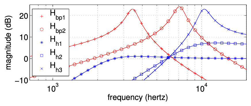
"Band pass filter #1 has a center frequency around 3440 Hz and band pass filter #2 has a center frequency around 7100 Hz. These band pass filters strongly accentuate the upper overtones of the square waves, while de-emphasizing their fundamental frequencies." (§4)
In plain words
Each band-pass filter is one op-amp with a small network in its feedback: two capacitors in series, with a resistor from their middle to ground, bridged by a resistor. The network passes a narrow band and the op-amp lifts it. Worked out from the parts' values, the first filter peaks at 3436 Hz, 23 dB up, and the second at 7096 Hz, 24 dB up, each about a sixth of its centre frequency wide.
Down at the oscillators' own pitches, the first filter is 9 dB down at 205 Hz, 32 dB below its peak, and the second 44 dB below its peak. So the six notes almost vanish, and what's left is their overtones around 3.4 kHz and 7.1 kHz: the bright, sizzling region of a real cymbal. The paper's equation 5 writes the first filter's response from its six parts; in SynthMaker, the circuit is simply solved.
Try it
circuit OscBankA setting output: 5 V V1 v5 gnd 5V Rin in gnd 100k # in isn't used: the oscillators run on their own # oscillator 1: 205.3 Hz U1 p1 c1 o1 comparator rails 0V 5V R40 o1 c1 560k C1 c1 gnd 18n Rh1 o1 p1 100k Rx1 v5 p1 28.571k Ry1 p1 gnd 26.087k R35 o1 out 120k # oscillator 2: 369.6 Hz U2 p2 c2 o2 comparator rails 0V 5V R41 o2 c2 560k C2 c2 gnd 10n Rh2 o2 p2 100k Rx2 v5 p2 28.571k Ry2 p2 gnd 26.087k R37 o2 out 120k # oscillator 3: 304.4 Hz U3 p3 c3 o3 comparator rails 0V 5V R42 o3 c3 680k C3 c3 gnd 10n Rh3 o3 p3 100k Rx3 v5 p3 28.571k Ry3 p3 gnd 26.087k R39 o3 out 120kendcircuit OscBankB setting input: 5 V setting output: 0.3 V, from 0.05 V to 1 V V1 v5 gnd 5V Rab in sum 40k # oscillators 1 to 3: three 120k in parallel # oscillator 4: 522.7 Hz U4 p4 c4 o4 comparator rails 0V 5V R43 o4 c4 220k C4 c4 gnd 18n Rh4 o4 p4 100k Rx4 v5 p4 28.571k Ry4 p4 gnd 26.087k R46 o4 sum 120k # oscillator 5: 800 Hz (R45 100k plus its trimmer at 43.74k) U5 p5 c5 o5 comparator rails 0V 5V R45 o5 c5 143.74k C5 c5 gnd 18n Rh5 o5 p5 100k Rx5 v5 p5 28.571k Ry5 p5 gnd 26.087k R48 o5 sum 120k # oscillator 6: 540 Hz (R44 150k plus its trimmer at 24.23k) U6 p6 c6 o6 comparator rails 0V 5V R44 o6 c6 174.23k C6 c6 gnd 22n Rh6 o6 p6 100k Rx6 v5 p6 28.571k Ry6 p6 gnd 26.087k R50 o6 sum 120k R53 sum gnd 1k # the two band-pass filters' inputs (their far ends sit at 0 V) C10 sum a1 3.3n R52 a1 gnd 33k C11 sum a2 1n R55 a2 gnd 22k # a tap to listen and to pass on Cl sum out 1u Rl out gnd 1Mendcircuit BandPass1 setting input: 0.3 V setting output: 0.58 V, from 0.1 V to 2 V C10 in a 3.3n R52 a m 33k U1 gnd m out opamp R57 out m 82k C13 m t 6.8n C14 t out 6.8n R56 t gnd 560endPress Play to see its frequencies after the circuit, at out.
Switch between the buttons and watch the Analyzer. "Before the filters" is step 3's chord. "Band-pass 1" keeps a hump of partials around 3.4 kHz and "Band-pass 2" one around 7.1 kHz. Both already sound more like metal than like notes. The input stage (C10 and R52, C11 and R55) also appears in OscBankB, as its load; here it carries the signal into the op-amp.
Step 5 · Every edge rings the filter (§4, Figure 5)
The paper says
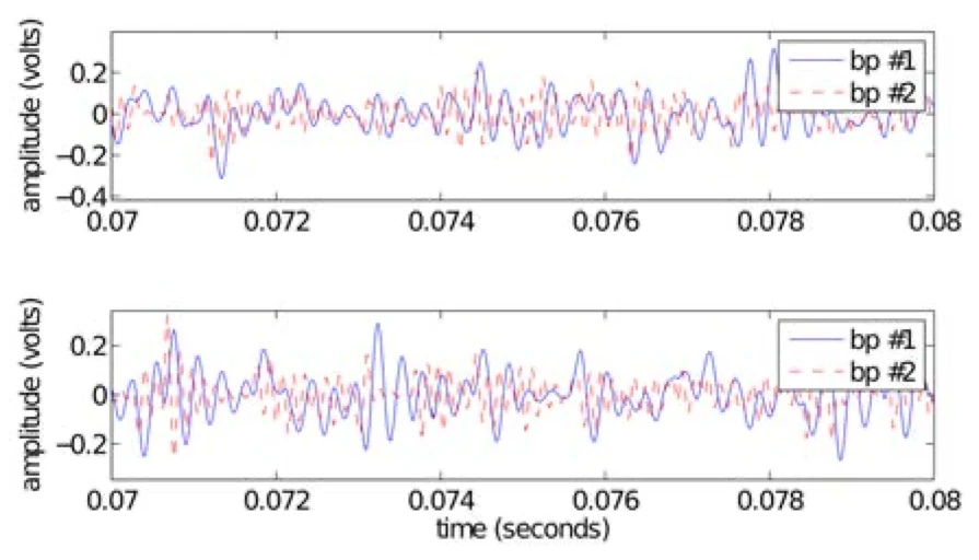
"Each time one of the six rectangular wave oscillators flips state, the edge kicks some more AC energy into each band pass filter." (§4)
In plain words
A narrow band-pass filter behaves like a bell. Strike it and it rings at its centre frequency, then dies away. Each edge of a square wave is a strike: a sudden step. The first filter answers with a burst at 3.4 kHz that fades with a time constant of about 0.56 ms.
Six oscillators make about 5,500 edges a second between them, at uneven times. So the bursts overlap all the time, each starting at its own moment. The result sounds like noise, but there's no noise source anywhere in the circuit: it's six square waves and a ringing filter.
Try it
circuit OscBankA setting output: 5 V V1 v5 gnd 5V Rin in gnd 100k # in isn't used: the oscillators run on their own # oscillator 1: 205.3 Hz U1 p1 c1 o1 comparator rails 0V 5V R40 o1 c1 560k C1 c1 gnd 18n Rh1 o1 p1 100k Rx1 v5 p1 28.571k Ry1 p1 gnd 26.087k R35 o1 out 120k # oscillator 2: 369.6 Hz U2 p2 c2 o2 comparator rails 0V 5V R41 o2 c2 560k C2 c2 gnd 10n Rh2 o2 p2 100k Rx2 v5 p2 28.571k Ry2 p2 gnd 26.087k R37 gnd out 120k # oscillator 3: 304.4 Hz U3 p3 c3 o3 comparator rails 0V 5V R42 o3 c3 680k C3 c3 gnd 10n Rh3 o3 p3 100k Rx3 v5 p3 28.571k Ry3 p3 gnd 26.087k R39 gnd out 120kendcircuit OscBankB setting input: 5 V setting output: 0.3 V, from 0.05 V to 1 V V1 v5 gnd 5V Rab in sum 40k # oscillators 1 to 3: three 120k in parallel # oscillator 4: 522.7 Hz U4 p4 c4 o4 comparator rails 0V 5V R43 o4 c4 220k C4 c4 gnd 18n Rh4 o4 p4 100k Rx4 v5 p4 28.571k Ry4 p4 gnd 26.087k R46 gnd sum 120k # oscillator 5: 800 Hz (R45 100k plus its trimmer at 43.74k) U5 p5 c5 o5 comparator rails 0V 5V R45 o5 c5 143.74k C5 c5 gnd 18n Rh5 o5 p5 100k Rx5 v5 p5 28.571k Ry5 p5 gnd 26.087k R48 gnd sum 120k # oscillator 6: 540 Hz (R44 150k plus its trimmer at 24.23k) U6 p6 c6 o6 comparator rails 0V 5V R44 o6 c6 174.23k C6 c6 gnd 22n Rh6 o6 p6 100k Rx6 v5 p6 28.571k Ry6 p6 gnd 26.087k R50 gnd sum 120k R53 sum gnd 1k # the two band-pass filters' inputs (their far ends sit at 0 V) C10 sum a1 3.3n R52 a1 gnd 33k C11 sum a2 1n R55 a2 gnd 22k # a tap to listen and to pass on Cl sum out 1u Rl out gnd 1Mendcircuit BandPass1 setting input: 0.3 V setting output: 0.58 V, from 0.1 V to 2 V C10 in a 3.3n R52 a m 33k U1 gnd m out opamp R57 out m 82k C13 m t 6.8n C14 t out 6.8n R56 t gnd 560endPress Play to see the wave after the circuit, at out.
"Oscillator 1 alone" joins the other five mixing resistors to ground instead of to their oscillators, which is how the paper works out one oscillator's share (§3). On the Scope, each edge of the 205 Hz square sets off one burst that fades before the next. Switch to "All six" and the bursts pile up into a shimmer.
Step 6 · The trigger and the accent (§5)
The paper says
"When Vid is present (logic high), a 1-ms long pulse is passed to the collector of Q6." (§5)
"The effect of the varying accent level is complex, and depends heavily on nonlinear downstream subcircuits: the attack smoother, envelope generators, and the swing-type VCAs." (§5)
In plain words
So far the oscillators buzz all the time. A note is a short pulse from the drum machine's sequencer, 1 ms long. Its height is the accent: from 7 V to 14 V, set by the machine's accent knob. Everything after it bends that height in its own nonlinear way, so a louder pulse changes the tone as well as the level.
The original lets the pulse through two transistors that check this voice is selected. We leave that logic out and start from the pulse itself. In SynthMaker, a Hit makes the pulse: it holds full level for 1 ms, then falls away in 5 ms, scaled by the note's velocity. It goes into the circuit's own input, trig, where 1 means 14 V.
From here on, the patch plays one band of the cymbal: the six oscillators, band-pass 1, then Band1. Band1 holds this band's trigger stage, envelope, amplifier and high-pass filter. Each of the next four steps watches a different point inside it.
Try it
circuit OscBankA setting output: 5 V V1 v5 gnd 5V Rin in gnd 100k # in isn't used: the oscillators run on their own # oscillator 1: 205.3 Hz U1 p1 c1 o1 comparator rails 0V 5V R40 o1 c1 560k C1 c1 gnd 18n Rh1 o1 p1 100k Rx1 v5 p1 28.571k Ry1 p1 gnd 26.087k R35 o1 out 120k # oscillator 2: 369.6 Hz U2 p2 c2 o2 comparator rails 0V 5V R41 o2 c2 560k C2 c2 gnd 10n Rh2 o2 p2 100k Rx2 v5 p2 28.571k Ry2 p2 gnd 26.087k R37 o2 out 120k # oscillator 3: 304.4 Hz U3 p3 c3 o3 comparator rails 0V 5V R42 o3 c3 680k C3 c3 gnd 10n Rh3 o3 p3 100k Rx3 v5 p3 28.571k Ry3 p3 gnd 26.087k R39 o3 out 120kendcircuit OscBankB setting input: 5 V setting output: 0.3 V, from 0.05 V to 1 V V1 v5 gnd 5V Rab in sum 40k # oscillators 1 to 3: three 120k in parallel # oscillator 4: 522.7 Hz U4 p4 c4 o4 comparator rails 0V 5V R43 o4 c4 220k C4 c4 gnd 18n Rh4 o4 p4 100k Rx4 v5 p4 28.571k Ry4 p4 gnd 26.087k R46 o4 sum 120k # oscillator 5: 800 Hz (R45 100k plus its trimmer at 43.74k) U5 p5 c5 o5 comparator rails 0V 5V R45 o5 c5 143.74k C5 c5 gnd 18n Rh5 o5 p5 100k Rx5 v5 p5 28.571k Ry5 p5 gnd 26.087k R48 o5 sum 120k # oscillator 6: 540 Hz (R44 150k plus its trimmer at 24.23k) U6 p6 c6 o6 comparator rails 0V 5V R44 o6 c6 174.23k C6 c6 gnd 22n Rh6 o6 p6 100k Rx6 v5 p6 28.571k Ry6 p6 gnd 26.087k R50 o6 sum 120k R53 sum gnd 1k # the two band-pass filters' inputs (their far ends sit at 0 V) C10 sum a1 3.3n R52 a1 gnd 33k C11 sum a2 1n R55 a2 gnd 22k # a tap to listen and to pass on Cl sum out 1u Rl out gnd 1Mendcircuit BandPass1 setting input: 0.3 V setting output: 0.58 V, from 0.1 V to 2 V C10 in a 3.3n R52 a m 33k U1 gnd m out opamp R57 out m 82k C13 m t 6.8n C14 t out 6.8n R56 t gnd 560endcircuit Band1 setting input: 0.58 V setting output: 15 V, from 1 V to 20 V setting decay: 25% in trig: from 0 V to 14 V V1 vcc gnd 15V V2 gnd vee 15V # attack smoother R84 trig b19 10k Q19 c19 b19 s 2N3904 R85 c19 d19 100 C35 d19 gnd 47u R86 vcc d19 100 # envelope generator 1 D8 s vb 1N4148 C41 vb gnd 1u R93 vb r93 470k P2 r93 r93 gnd 2M decay # VR2, the decay knob: a variable resistor, 0 to 2M Q20 vcc vb e20 2N3904 R92 e20 eg13 33k R89 eg13 gnd 10k R105 e20 eg12 33k C45 eg12 gnd 2.2u # swing-type VCA 1 C46 in b18 22n R102 vcc r102 1M R103 r102 b18 1M Q18 c18 b18 e18 2N3904 R101 e18 gnd 100 D12 v1 c18 1N4148 R104 eg12 v1 22k # high-pass filter 1 C48 v1 h1 1.5n C59 h1 b25 1.5n R124 h1 vh1 22k R127 b25 gnd 82k Q25 vcc b25 vh1 2N3904 R126 vh1 vee 22k # a tap to listen and to pass on Cl vh1 out 1u Rl out gnd 1MendPress Play to see the wave inside the circuit, at trig.
The Scope watches trig: a spike to 14 V that's gone within a few milliseconds, once every two seconds. Listen to each hit on both buttons. "Low accent" is quieter, but the paper says the accent's effect is complex, so listen for the tone changing too, not just the level.
Step 7 · The attack smoother (§6, equation 6, Figure 6)
The paper says
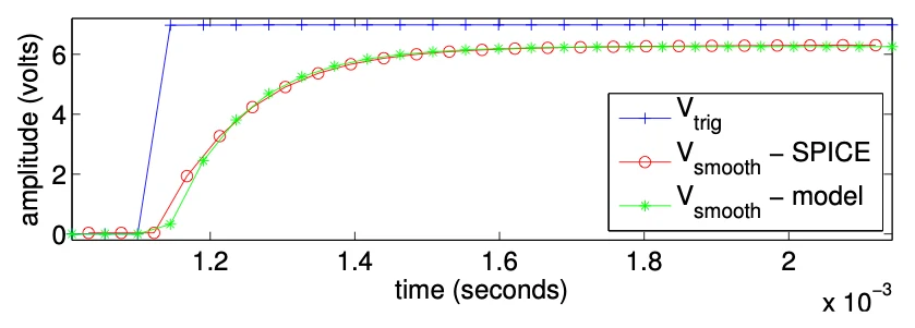
"Although the physics of this sub-circuit are difficult to work out in closed form, a one pole filter of the following form approximates the behavior of this circuit" (§6)
In plain words
The pulse goes into the base of Q19, a transistor wired as an emitter follower. Its emitter, s, follows its base about 0.7 V lower, and it can push a lot of current into whatever comes next. The paper fits the stage with two numbers: a drop of 0.7258 V, then a gentle low-pass with a time constant of 0.10 ms (1.0244 × 10⁻⁴ s). So the pulse arrives a little lower and with its front corner rounded.
That rounding is the cymbal's attack. A perfectly sharp front would click; this one takes about a tenth of a millisecond to rise. Our circuit has the real parts, R84 into Q19, with its collector fed through 100 Ω and held up by 47 µF, so the rounding you see comes from the circuit itself, not from a fitted filter.
Try it
circuit OscBankA setting output: 5 V V1 v5 gnd 5V Rin in gnd 100k # in isn't used: the oscillators run on their own # oscillator 1: 205.3 Hz U1 p1 c1 o1 comparator rails 0V 5V R40 o1 c1 560k C1 c1 gnd 18n Rh1 o1 p1 100k Rx1 v5 p1 28.571k Ry1 p1 gnd 26.087k R35 o1 out 120k # oscillator 2: 369.6 Hz U2 p2 c2 o2 comparator rails 0V 5V R41 o2 c2 560k C2 c2 gnd 10n Rh2 o2 p2 100k Rx2 v5 p2 28.571k Ry2 p2 gnd 26.087k R37 o2 out 120k # oscillator 3: 304.4 Hz U3 p3 c3 o3 comparator rails 0V 5V R42 o3 c3 680k C3 c3 gnd 10n Rh3 o3 p3 100k Rx3 v5 p3 28.571k Ry3 p3 gnd 26.087k R39 o3 out 120kendcircuit OscBankB setting input: 5 V setting output: 0.3 V, from 0.05 V to 1 V V1 v5 gnd 5V Rab in sum 40k # oscillators 1 to 3: three 120k in parallel # oscillator 4: 522.7 Hz U4 p4 c4 o4 comparator rails 0V 5V R43 o4 c4 220k C4 c4 gnd 18n Rh4 o4 p4 100k Rx4 v5 p4 28.571k Ry4 p4 gnd 26.087k R46 o4 sum 120k # oscillator 5: 800 Hz (R45 100k plus its trimmer at 43.74k) U5 p5 c5 o5 comparator rails 0V 5V R45 o5 c5 143.74k C5 c5 gnd 18n Rh5 o5 p5 100k Rx5 v5 p5 28.571k Ry5 p5 gnd 26.087k R48 o5 sum 120k # oscillator 6: 540 Hz (R44 150k plus its trimmer at 24.23k) U6 p6 c6 o6 comparator rails 0V 5V R44 o6 c6 174.23k C6 c6 gnd 22n Rh6 o6 p6 100k Rx6 v5 p6 28.571k Ry6 p6 gnd 26.087k R50 o6 sum 120k R53 sum gnd 1k # the two band-pass filters' inputs (their far ends sit at 0 V) C10 sum a1 3.3n R52 a1 gnd 33k C11 sum a2 1n R55 a2 gnd 22k # a tap to listen and to pass on Cl sum out 1u Rl out gnd 1Mendcircuit BandPass1 setting input: 0.3 V setting output: 0.58 V, from 0.1 V to 2 V C10 in a 3.3n R52 a m 33k U1 gnd m out opamp R57 out m 82k C13 m t 6.8n C14 t out 6.8n R56 t gnd 560endcircuit Band1 setting input: 0.58 V setting output: 15 V, from 1 V to 20 V setting decay: 25% in trig: from 0 V to 14 V V1 vcc gnd 15V V2 gnd vee 15V # attack smoother R84 trig b19 10k Q19 c19 b19 s 2N3904 R85 c19 d19 100 C35 d19 gnd 47u R86 vcc d19 100 # envelope generator 1 D8 s vb 1N4148 C41 vb gnd 1u R93 vb r93 470k P2 r93 r93 gnd 2M decay # VR2, the decay knob: a variable resistor, 0 to 2M Q20 vcc vb e20 2N3904 R92 e20 eg13 33k R89 eg13 gnd 10k R105 e20 eg12 33k C45 eg12 gnd 2.2u # swing-type VCA 1 C46 in b18 22n R102 vcc r102 1M R103 r102 b18 1M Q18 c18 b18 e18 2N3904 R101 e18 gnd 100 D12 v1 c18 1N4148 R104 eg12 v1 22k # high-pass filter 1 C48 v1 h1 1.5n C59 h1 b25 1.5n R124 h1 vh1 22k R127 b25 gnd 82k Q25 vcc b25 vh1 2N3904 R126 vh1 vee 22k # a tap to listen and to pass on Cl vh1 out 1u Rl out gnd 1MendPress Play to see the wave inside the circuit, at s.
The Scope watches s, Q19's emitter. Compare it with step 6's spike: lower by the transistor's drop, and rounded at the front.
Step 8 · The envelope generators (§7, Figure 7)
The paper says
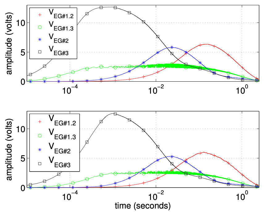
"A simplified diode model is leveraged to separate the attack and release phases, allowing simulation by numerical solution of a switched first-order ordinary differential equation (ODE)." (§7)
"At higher decay settings, the RC time constant of decay increases, and the decay for this band is longer." (§7)
In plain words
The smoothed pulse charges a capacitor, C41 (1 µF), through a diode, D8. While the pulse is up, the diode conducts and the capacitor follows it, one diode drop lower (the paper fits 0.59 V). When the pulse ends, the diode stops conducting and acts as an open switch. That's the paper's "switched" equation: one rule while charging, another while letting go.
Letting go, C41 drains through R93 (470 kΩ) and the decay knob, VR2, a 0 to 2 MΩ variable resistor. That makes a time constant from 0.47 s to 2.47 s. At 25%, the setting the paper renders with, it's about 0.97 s.
Q20 buffers that voltage and feeds two outputs. EG 1.2, softened by R105 and C45 (33 kΩ and 2.2 µF), drives band 1's amplifier. EG 1.3, a divider giving about a quarter of it, helps drive band 2's. Bands 2 and 3 have envelope generators of their own, with fixed decays. So the decay knob shapes band 1 and part of band 2, and the rest of the cymbal keeps its own time.
Try it
circuit OscBankA setting output: 5 V V1 v5 gnd 5V Rin in gnd 100k # in isn't used: the oscillators run on their own # oscillator 1: 205.3 Hz U1 p1 c1 o1 comparator rails 0V 5V R40 o1 c1 560k C1 c1 gnd 18n Rh1 o1 p1 100k Rx1 v5 p1 28.571k Ry1 p1 gnd 26.087k R35 o1 out 120k # oscillator 2: 369.6 Hz U2 p2 c2 o2 comparator rails 0V 5V R41 o2 c2 560k C2 c2 gnd 10n Rh2 o2 p2 100k Rx2 v5 p2 28.571k Ry2 p2 gnd 26.087k R37 o2 out 120k # oscillator 3: 304.4 Hz U3 p3 c3 o3 comparator rails 0V 5V R42 o3 c3 680k C3 c3 gnd 10n Rh3 o3 p3 100k Rx3 v5 p3 28.571k Ry3 p3 gnd 26.087k R39 o3 out 120kendcircuit OscBankB setting input: 5 V setting output: 0.3 V, from 0.05 V to 1 V V1 v5 gnd 5V Rab in sum 40k # oscillators 1 to 3: three 120k in parallel # oscillator 4: 522.7 Hz U4 p4 c4 o4 comparator rails 0V 5V R43 o4 c4 220k C4 c4 gnd 18n Rh4 o4 p4 100k Rx4 v5 p4 28.571k Ry4 p4 gnd 26.087k R46 o4 sum 120k # oscillator 5: 800 Hz (R45 100k plus its trimmer at 43.74k) U5 p5 c5 o5 comparator rails 0V 5V R45 o5 c5 143.74k C5 c5 gnd 18n Rh5 o5 p5 100k Rx5 v5 p5 28.571k Ry5 p5 gnd 26.087k R48 o5 sum 120k # oscillator 6: 540 Hz (R44 150k plus its trimmer at 24.23k) U6 p6 c6 o6 comparator rails 0V 5V R44 o6 c6 174.23k C6 c6 gnd 22n Rh6 o6 p6 100k Rx6 v5 p6 28.571k Ry6 p6 gnd 26.087k R50 o6 sum 120k R53 sum gnd 1k # the two band-pass filters' inputs (their far ends sit at 0 V) C10 sum a1 3.3n R52 a1 gnd 33k C11 sum a2 1n R55 a2 gnd 22k # a tap to listen and to pass on Cl sum out 1u Rl out gnd 1Mendcircuit BandPass1 setting input: 0.3 V setting output: 0.58 V, from 0.1 V to 2 V C10 in a 3.3n R52 a m 33k U1 gnd m out opamp R57 out m 82k C13 m t 6.8n C14 t out 6.8n R56 t gnd 560endcircuit Band1 setting input: 0.58 V setting output: 15 V, from 1 V to 20 V setting decay: 25% in trig: from 0 V to 14 V V1 vcc gnd 15V V2 gnd vee 15V # attack smoother R84 trig b19 10k Q19 c19 b19 s 2N3904 R85 c19 d19 100 C35 d19 gnd 47u R86 vcc d19 100 # envelope generator 1 D8 s vb 1N4148 C41 vb gnd 1u R93 vb r93 470k P2 r93 r93 gnd 2M decay # VR2, the decay knob: a variable resistor, 0 to 2M Q20 vcc vb e20 2N3904 R92 e20 eg13 33k R89 eg13 gnd 10k R105 e20 eg12 33k C45 eg12 gnd 2.2u # swing-type VCA 1 C46 in b18 22n R102 vcc r102 1M R103 r102 b18 1M Q18 c18 b18 e18 2N3904 R101 e18 gnd 100 D12 v1 c18 1N4148 R104 eg12 v1 22k # high-pass filter 1 C48 v1 h1 1.5n C59 h1 b25 1.5n R124 h1 vh1 22k R127 b25 gnd 82k Q25 vcc b25 vh1 2N3904 R126 vh1 vee 22k # a tap to listen and to pass on Cl vh1 out 1u Rl out gnd 1MendPress Play to see the wave inside the circuit, at eg12.
The Scope watches eg12, the envelope that drives band 1's amplifier: a quick rise, then a long fall. Turn decay up and the fall stretches, and so does the sound. At 100%, the next hit arrives before the last one has died away.
Step 9 · The swing-type amplifier (§8, Figure 8)
The paper says
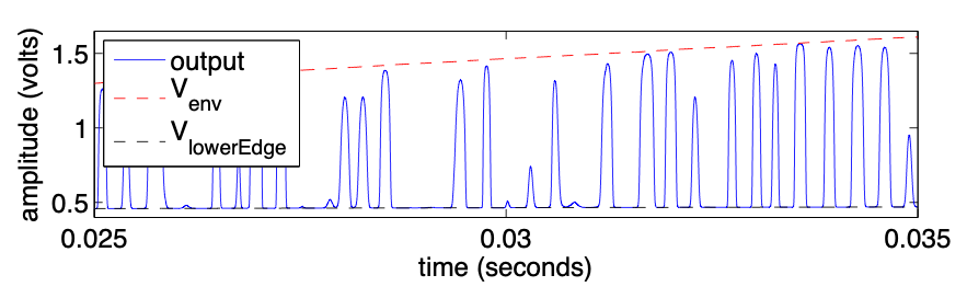
"Here, it leads to clipping—a wild swing of the output between VEG#1.2 and VlowerEdge, apparent intended behavior." (§8.1)
"Without the diode, the output of the VCA would never shut all the way off." (§8.3)
In plain words
This amplifier is one transistor, Q18, with a twist. Its collector isn't fed from a fixed supply: it's fed from the envelope, through R104 (22 kΩ) and the diode D12. Its base gets a small, steady current from +15 V through 2 MΩ. With our transistor model, that is enough to turn it fully on, so far on that it saturates. That's the biasing the paper says depends on each transistor's gain.
The band-pass signal arrives through C46, and each downward swing turns the transistor off. So the output jumps between two levels: up to the envelope voltage when the transistor is off, down to a low "lower edge" when it's on. It is a wild swing, as the paper says: clipped bursts whose height is the envelope. Because the height follows the envelope, it works as a voltage-controlled amplifier, a very rough one, and the clipping adds edges and partials of its own. The paper approximates all this with fitted curves (equations 13 to 15); SynthMaker solves the transistor itself.
Try it
circuit OscBankA setting output: 5 V V1 v5 gnd 5V Rin in gnd 100k # in isn't used: the oscillators run on their own # oscillator 1: 205.3 Hz U1 p1 c1 o1 comparator rails 0V 5V R40 o1 c1 560k C1 c1 gnd 18n Rh1 o1 p1 100k Rx1 v5 p1 28.571k Ry1 p1 gnd 26.087k R35 o1 out 120k # oscillator 2: 369.6 Hz U2 p2 c2 o2 comparator rails 0V 5V R41 o2 c2 560k C2 c2 gnd 10n Rh2 o2 p2 100k Rx2 v5 p2 28.571k Ry2 p2 gnd 26.087k R37 o2 out 120k # oscillator 3: 304.4 Hz U3 p3 c3 o3 comparator rails 0V 5V R42 o3 c3 680k C3 c3 gnd 10n Rh3 o3 p3 100k Rx3 v5 p3 28.571k Ry3 p3 gnd 26.087k R39 o3 out 120kendcircuit OscBankB setting input: 5 V setting output: 0.3 V, from 0.05 V to 1 V V1 v5 gnd 5V Rab in sum 40k # oscillators 1 to 3: three 120k in parallel # oscillator 4: 522.7 Hz U4 p4 c4 o4 comparator rails 0V 5V R43 o4 c4 220k C4 c4 gnd 18n Rh4 o4 p4 100k Rx4 v5 p4 28.571k Ry4 p4 gnd 26.087k R46 o4 sum 120k # oscillator 5: 800 Hz (R45 100k plus its trimmer at 43.74k) U5 p5 c5 o5 comparator rails 0V 5V R45 o5 c5 143.74k C5 c5 gnd 18n Rh5 o5 p5 100k Rx5 v5 p5 28.571k Ry5 p5 gnd 26.087k R48 o5 sum 120k # oscillator 6: 540 Hz (R44 150k plus its trimmer at 24.23k) U6 p6 c6 o6 comparator rails 0V 5V R44 o6 c6 174.23k C6 c6 gnd 22n Rh6 o6 p6 100k Rx6 v5 p6 28.571k Ry6 p6 gnd 26.087k R50 o6 sum 120k R53 sum gnd 1k # the two band-pass filters' inputs (their far ends sit at 0 V) C10 sum a1 3.3n R52 a1 gnd 33k C11 sum a2 1n R55 a2 gnd 22k # a tap to listen and to pass on Cl sum out 1u Rl out gnd 1Mendcircuit BandPass1 setting input: 0.3 V setting output: 0.58 V, from 0.1 V to 2 V C10 in a 3.3n R52 a m 33k U1 gnd m out opamp R57 out m 82k C13 m t 6.8n C14 t out 6.8n R56 t gnd 560endcircuit Band1 setting input: 0.58 V setting output: 15 V, from 1 V to 20 V setting decay: 25% in trig: from 0 V to 14 V V1 vcc gnd 15V V2 gnd vee 15V # attack smoother R84 trig b19 10k Q19 c19 b19 s 2N3904 R85 c19 d19 100 C35 d19 gnd 47u R86 vcc d19 100 # envelope generator 1 D8 s vb 1N4148 C41 vb gnd 1u R93 vb r93 470k P2 r93 r93 gnd 2M decay # VR2, the decay knob: a variable resistor, 0 to 2M Q20 vcc vb e20 2N3904 R92 e20 eg13 33k R89 eg13 gnd 10k R105 e20 eg12 33k C45 eg12 gnd 2.2u # swing-type VCA 1 C46 in b18 22n R102 vcc r102 1M R103 r102 b18 1M Q18 c18 b18 e18 2N3904 R101 e18 gnd 100 D12 v1 c18 1N4148 R104 eg12 v1 22k # high-pass filter 1 C48 v1 h1 1.5n C59 h1 b25 1.5n R124 h1 vh1 22k R127 b25 gnd 82k Q25 vcc b25 vh1 2N3904 R126 vh1 vee 22k # a tap to listen and to pass on Cl vh1 out 1u Rl out gnd 1MendPress Play to see the wave inside the circuit, at v1.
The Scope watches v1, the amplifier's output: blocky bursts that shrink as the envelope falls. "Without the diode" puts a 1 Ω wire in its place. The paper says the diode is what lets the output close completely, so listen to how each hit ends on both buttons.
Step 10 · Three high-pass filters (§9, Figure 4)
The paper says
"Using an op-amp in place of an emitter-follower allows for the design of non-unity-gain buffering. This manifests as resonance at the corner frequency (around 10500 Hz) in the magnitude response." (§9)
In plain words
The cymbal has three bands, each with its own amplifier and envelope. Band 1 takes band-pass 1, around 3.4 kHz. Bands 2 and 3 both take band-pass 2, around 7.1 kHz, with different envelopes. Each band ends with a high-pass filter that clears out the lows the clipping and the envelope's movement leave behind.
Worked out from the parts' values: - Band 1: a second-order high-pass with an emitter follower, Q25, as its buffer. It's 3 dB down at 2 kHz and flat above. - Band 2: a second-order high-pass with an op-amp at a gain of 2. It rises to 7 dB up around 12.5 kHz. - Band 3: a third-order high-pass with an op-amp at a gain of 2.8. It resonates, 23 dB up at about 10.4 kHz: the paper's "around 10500 Hz". That peak is band 3's bright, glassy ring.
Bands 2 and 3 are two more circuits, each with its own copy of the trigger stage from step 6, so each can play on its own.
Try it
circuit OscBankA setting output: 5 V V1 v5 gnd 5V Rin in gnd 100k # in isn't used: the oscillators run on their own # oscillator 1: 205.3 Hz U1 p1 c1 o1 comparator rails 0V 5V R40 o1 c1 560k C1 c1 gnd 18n Rh1 o1 p1 100k Rx1 v5 p1 28.571k Ry1 p1 gnd 26.087k R35 o1 out 120k # oscillator 2: 369.6 Hz U2 p2 c2 o2 comparator rails 0V 5V R41 o2 c2 560k C2 c2 gnd 10n Rh2 o2 p2 100k Rx2 v5 p2 28.571k Ry2 p2 gnd 26.087k R37 o2 out 120k # oscillator 3: 304.4 Hz U3 p3 c3 o3 comparator rails 0V 5V R42 o3 c3 680k C3 c3 gnd 10n Rh3 o3 p3 100k Rx3 v5 p3 28.571k Ry3 p3 gnd 26.087k R39 o3 out 120kendcircuit OscBankB setting input: 5 V setting output: 0.3 V, from 0.05 V to 1 V V1 v5 gnd 5V Rab in sum 40k # oscillators 1 to 3: three 120k in parallel # oscillator 4: 522.7 Hz U4 p4 c4 o4 comparator rails 0V 5V R43 o4 c4 220k C4 c4 gnd 18n Rh4 o4 p4 100k Rx4 v5 p4 28.571k Ry4 p4 gnd 26.087k R46 o4 sum 120k # oscillator 5: 800 Hz (R45 100k plus its trimmer at 43.74k) U5 p5 c5 o5 comparator rails 0V 5V R45 o5 c5 143.74k C5 c5 gnd 18n Rh5 o5 p5 100k Rx5 v5 p5 28.571k Ry5 p5 gnd 26.087k R48 o5 sum 120k # oscillator 6: 540 Hz (R44 150k plus its trimmer at 24.23k) U6 p6 c6 o6 comparator rails 0V 5V R44 o6 c6 174.23k C6 c6 gnd 22n Rh6 o6 p6 100k Rx6 v5 p6 28.571k Ry6 p6 gnd 26.087k R50 o6 sum 120k R53 sum gnd 1k # the two band-pass filters' inputs (their far ends sit at 0 V) C10 sum a1 3.3n R52 a1 gnd 33k C11 sum a2 1n R55 a2 gnd 22k # a tap to listen and to pass on Cl sum out 1u Rl out gnd 1Mendcircuit BandPass1 setting input: 0.3 V setting output: 0.58 V, from 0.1 V to 2 V C10 in a 3.3n R52 a m 33k U1 gnd m out opamp R57 out m 82k C13 m t 6.8n C14 t out 6.8n R56 t gnd 560endcircuit Band1 setting input: 0.58 V setting output: 15 V, from 1 V to 20 V setting decay: 25% in trig: from 0 V to 14 V V1 vcc gnd 15V V2 gnd vee 15V # attack smoother R84 trig b19 10k Q19 c19 b19 s 2N3904 R85 c19 d19 100 C35 d19 gnd 47u R86 vcc d19 100 # envelope generator 1 D8 s vb 1N4148 C41 vb gnd 1u R93 vb r93 470k P2 r93 r93 gnd 2M decay # VR2, the decay knob: a variable resistor, 0 to 2M Q20 vcc vb e20 2N3904 R92 e20 eg13 33k R89 eg13 gnd 10k R105 e20 eg12 33k C45 eg12 gnd 2.2u # swing-type VCA 1 C46 in b18 22n R102 vcc r102 1M R103 r102 b18 1M Q18 c18 b18 e18 2N3904 R101 e18 gnd 100 D12 v1 c18 1N4148 R104 eg12 v1 22k # high-pass filter 1 C48 v1 h1 1.5n C59 h1 b25 1.5n R124 h1 vh1 22k R127 b25 gnd 82k Q25 vcc b25 vh1 2N3904 R126 vh1 vee 22k # a tap to listen and to pass on Cl vh1 out 1u Rl out gnd 1MendPress Play to see its frequencies after the circuit, at out.
Play each band alone and watch the Analyzer. Band 1 is the lowest and fullest, band 2 brighter, and band 3 has a strong peak near 10 kHz. Band 3's envelope is fixed, while band 2's follows the decay knob in part, through EG 1.3.
Step 11 · The tone stage (§10, Figure 9)
The paper says
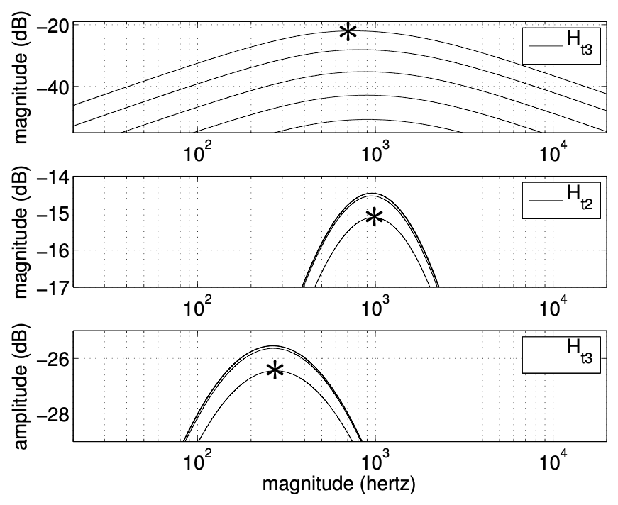
"The primary effect of the tone control is to change the amount of attenuation in the third band. However, the center frequencies of all bands and the attenuation of the first and second bands are also somewhat affected." (§10)
In plain words
The three bands meet in a network of resistors and capacitors with one knob, tone, a 20 kΩ pot. One end of its track is on band 3's path, the other goes through 2.2 kΩ to the point where bands 1 and 2 join, and its wiper goes to ground. Turn it up and band 3 gets through while bands 1 and 2 are pulled down a little. Turn it down and the reverse. Band 1 comes in through 100 kΩ with 3.3 nF to ground, so it arrives softened.
Because everything in the network leans on everything else, one knob moves several things at once, as the paper notes, just like a guitar amp's tone stack. The paper writes the network as three fifth-order transfer functions, too long to print. In SynthMaker, the network is just its parts.
ToneLevel takes band 1 at its input and bands 2 and 3 at two inputs of its own, h2 and h3. Bands 2 and 3 arrive from op-amp outputs, so the cut is exact; band 1 from an emitter follower, which is very nearly so. The whole voice is wired up in step 14.
Try it
# SynthMaker · Cymbalvoice = Voice()hit = Hit(hold: 1 ms, decay: 5 ms)osc13 = OscBankA()osc46 = OscBankB()bp1 = BandPass1()bp2 = BandPass2()band1 = Band1(decay: 25%)band2 = Band2(decay: 25%)band3 = Band3()mix = ToneLevel(tone: 50%, level: 50%)osc13 -> osc46 -> bp1 -> band1 -> mix -> outosc46 -> bp2 -> band2 -> mix.h2bp2 -> band3 -> mix.h3voice.gate -> hit -> band1.trighit -> band2.trighit -> band3.trigThe whole voice: each of its circuits is drawn in its own step above, and the patch beside this wires them together.
Press Play to see its frequencies after the circuit, at out.
Hold the Analyzer in view and turn tone from one end to the other. The top end, around 10 kHz, comes and goes the most: that's band 3. But the lower bands shift too.
Step 12 · The output buffer and level (§11, Figure 10)
The paper says
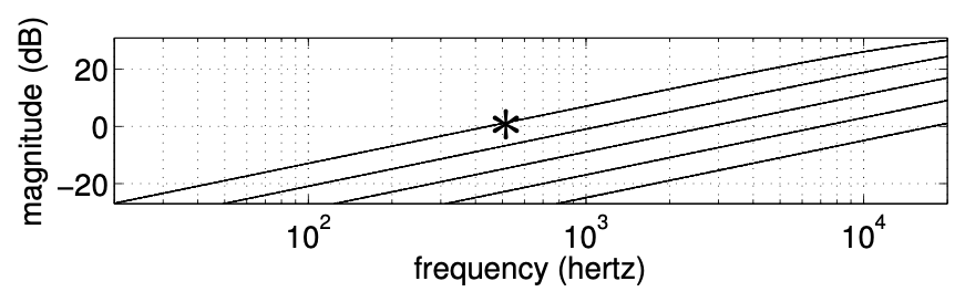
"In addition to attenuation, the output level control buffer also acts as a differentiator in the audio band—it has a frequency response with a 6 dB/octave rising slope." (§11)
In plain words
The mixed bands reach op-amp U6 through a capacitor, C90 (10 nF), into its − input, which the op-amp holds at 0 V. Current through a capacitor is proportional to how fast the voltage across it changes, so the higher the frequency, the more current flows. The op-amp turns that current into the output voltage. The result is a differentiator: each octave up comes out twice as loud, 6 dB more. A cymbal wants its top end, and this stage tilts the whole sound that way.
The level knob, VR6, is a 100 kΩ pot with an audio taper, wired as a variable resistor in series with C78 (33 µF). Together with R128 (470 kΩ) and C77 (220 pF), it sets how much current becomes how much voltage: turn it down and the gain drops. At half way, an audio-taper pot is at a tenth of its track, 10 kΩ. As the paper's Figure 10 shows, the knob also bends the curve's shape a little (why audio-taper pots exist).
Try it
# SynthMaker · Cymbalvoice = Voice()hit = Hit(hold: 1 ms, decay: 5 ms)osc13 = OscBankA()osc46 = OscBankB()bp1 = BandPass1()bp2 = BandPass2()band1 = Band1(decay: 25%)band2 = Band2(decay: 25%)band3 = Band3()mix = ToneLevel(tone: 50%, level: 50%)osc13 -> osc46 -> bp1 -> band1 -> mix -> outosc46 -> bp2 -> band2 -> mix.h2bp2 -> band3 -> mix.h3voice.gate -> hit -> band1.trighit -> band2.trighit -> band3.trigThe whole voice: each of its circuits is drawn in its own step above, and the patch beside this wires them together.
Press Play to see its frequencies after the circuit, at out.
Turn level down and up. It isn't a plain volume control: listen to the balance between the hiss and the body of the hit as you turn.
Step 13 · Making it digital (§12)
The paper says
"All examples in this work are rendered at 4×oversampling (fs = 44100 ×4 Hz), so they suffer only negligibly from frequency warping." (§12)
"To break the delay-free loops arising from mutual interaction between the VCAs and envelope generators, fictitious unit delays are inserted." (§12)
In plain words
The paper turns each block's analogue equations into digital filters with the bilinear transform. That transform is accurate at low frequencies but squeezes high ones downwards: frequency warping. The cymbal lives up high, so it matters. Band 3's 10.4 kHz peak would land at about 9.1 kHz at 48 kHz. At twice the rate it lands at about 10.0 kHz, and at four times, 10.3 kHz. The paper renders at 4× and also tunes each filter so its key frequency lands exactly.
SynthMaker's circuits use the same transform, since each capacitor is solved by the trapezoidal rule. So the same cure applies: oversampling. Circuits with transistors, diodes or comparators run at 2× unless told otherwise.
The second quote is about loops. In the original, the amplifiers draw current from the envelopes and so pull them down, while the envelopes set the amplifiers. Computing one block after another, the paper has to break that loop with a delay of one sample. SynthMaker solves all the parts of one circuit together, every sample, so an envelope and its amplifier, which share a circuit, need no such delay. The circuits are cut only where the signal flows one way.
Try it
# SynthMaker · Cymbalvoice = Voice()hit = Hit(hold: 1 ms, decay: 5 ms)osc13 = OscBankA()osc46 = OscBankB()bp1 = BandPass1()bp2 = BandPass2()band1 = Band1(decay: 25%)band2 = Band2(decay: 25%)band3 = Band3()mix = ToneLevel(tone: 50%, level: 50%)osc13 -> osc46 -> bp1 -> band1 -> mix -> outosc46 -> bp2 -> band2 -> mix.h2bp2 -> band3 -> mix.h3voice.gate -> hit -> band1.trighit -> band2.trighit -> band3.trigThe whole voice: each of its circuits is drawn in its own step above, and the patch beside this wires them together.
The whole voice: each of its circuits is drawn in its own step above, and the patch beside this wires them together.
The whole voice: each of its circuits is drawn in its own step above, and the patch beside this wires them together.
Press Play to see its frequencies after the circuit, at out.
Compare "1×" with "4×, as the paper" on the Analyzer. At 1×, band 3's filter peak sits lower, as above, but that isn't what you hear most: the hit comes out louder and harsher, about 1 to 2 dB overall and up to 4.5 dB around 10 kHz. The clipping amplifiers make partials above half the sample rate, and at 1× they fold back down into the audible range (aliasing). "2×" is close to "4×": band by band, both come within about half a decibel of a SPICE simulation of the whole circuit.
Step 14 · The whole voice (§13, Figure 11)
The paper says
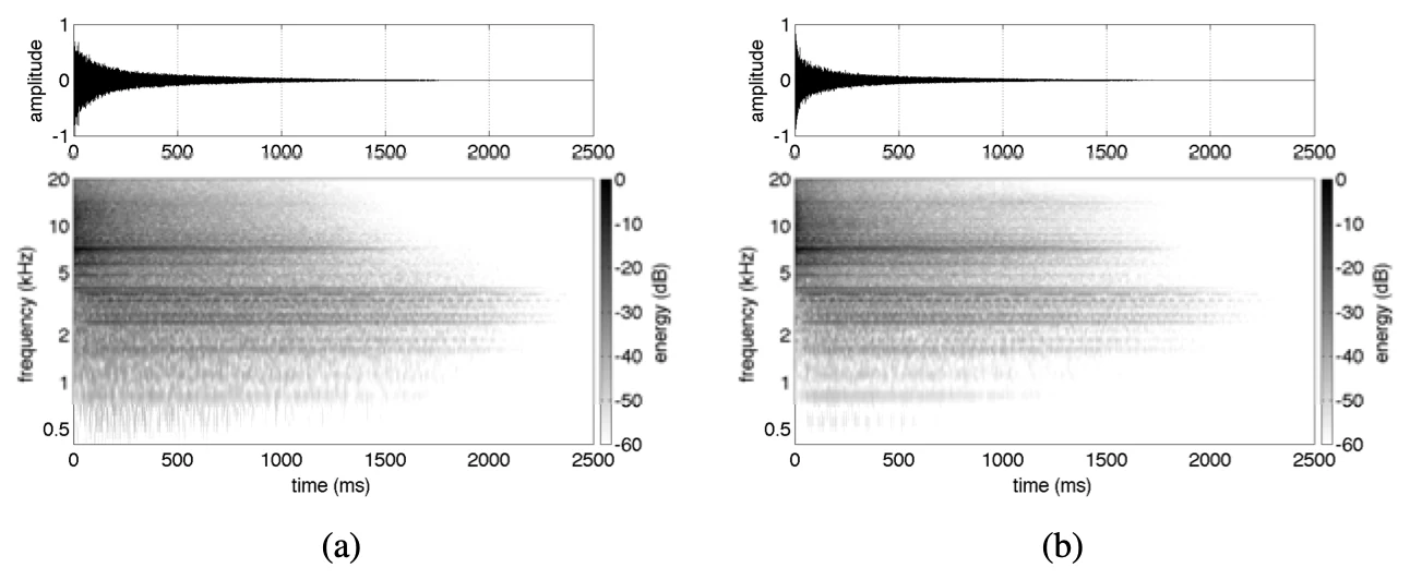
"Fig. 11(b) is the same output from the physical model, which shows good agreement with the SPICE simulation." (§13)
"Some parts of the model are oversimplified. The VCAs and envelope generators, in particular, are modeled with significant simplifications, and some of their nonlinearities ignored." (§12)
In plain words
Here is everything together: six oscillators, two band-pass filters, three bands each with its trigger stage, envelope, swing amplifier and high-pass filter, then the tone stage and the output. The paper checks its whole model against a SPICE simulation of the whole circuit, Figure 11 (a) against (b), with decay at 25%, tone at 50% and level at 50%. Those are the defaults below.
The paper is honest about where its model is simplest: the amplifiers and the envelopes, fitted with curves. Those are the parts SynthMaker solves as circuits, transistor by transistor. That isn't the same as being exact (see "What we left out"), but none of it is fitted.
Try it
# SynthMaker · Cymbalvoice = Voice()hit = Hit(hold: 1 ms, decay: 5 ms)osc13 = OscBankA()osc46 = OscBankB()bp1 = BandPass1()bp2 = BandPass2()band1 = Band1(decay: 25%)band2 = Band2(decay: 25%)band3 = Band3()mix = ToneLevel(tone: 50%, level: 50%)osc13 -> osc46 -> bp1 -> band1 -> mix -> outosc46 -> bp2 -> band2 -> mix.h2bp2 -> band3 -> mix.h3voice.gate -> hit -> band1.trighit -> band2.trighit -> band3.trig# SynthMaker · Cymbalvoice = Voice()hit = Hit(hold: 1 ms, decay: 5 ms)osc13 = OscBankA()osc46 = OscBankB()bp1 = BandPass1()bp2 = BandPass2()band1 = Band1(decay: 25%)band2 = Band2(decay: 25%)band3 = Band3()mix = ToneLevel(tone: 50%, level: 50%)osc13 -> osc46 -> bp1 -> band1 -> mix -> outosc46 -> bp2 -> band2 -> mix.h2bp2 -> band3 -> mix.h3voice.gate -> hit -> band1.trighit -> band2.trighit -> band3.trigThe whole voice: each of its circuits is drawn in its own step above, and the patch beside this wires them together.
Press Play to see its frequencies after the circuit, at out.
The circuits are steps 3, 4, 6, 10 and 11's. A Hit makes the 1 ms trigger from each note, at full height (the strongest accent); step 6 shows the softer accent. The decay knob turns both band 1's and band 2's decay, as the single knob on the original does. Play with all three knobs; then try the bends in step 15.
Step 15 · Circuit bends (§12–13, Figure 11)
The paper says
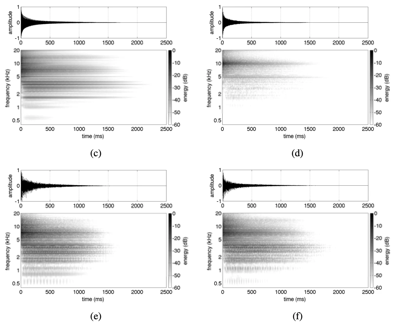
"One bend that has a surprising effect on the sound is replacing R53 with a logarithmic potentiometer." (§12)
"Rather than producing a glut of inharmonically related partials, as in the circuit’s stock configuration (or a real, physical cymbal), these harmonically related partials have a comb-filter- or resonator-like effect." (§13)
"This will affect the tuning, amplitude, and duty cycle of each oscillator. Due to the nonlinearity of the VCAs, this will have complex timbral consequences." (§13)
In plain words
Because the model is built from parts, bending it means changing parts, as circuit benders do with a soldering iron. The paper tries four bends. - A chord instead of a clang (c): mute three oscillators and tune the other three to an open A major chord. Their partials now line up, and the cymbal turns into a ringing, comb-filtered chord. We keep oscillators 1, 5 and 6, tuned to A3, E4 and C♯5. - The filters retuned (d): halve R56 and R58, the resistors in the middle of each band-pass network. Worked out from the values, the peaks move up to about 4.9 kHz and 10 kHz and get narrower, and most of the low content goes. - Less into the filters (e): R53 sets how much of the six oscillators reaches the filters (step 3). Lower it and less gets through, so the amplifiers only clip now and then, which changes the texture. We use 330 Ω in place of 1 kΩ. - Voltage starve (f): run the oscillator chip at half its 5 V supply. A real Schmitt-trigger gate's thresholds don't scale neatly with its supply, so pitch, level and duty all shift at once. The paper estimates them from the data sheet.
Try it
# SynthMaker · Cymbalvoice = Voice()hit = Hit(hold: 1 ms, decay: 5 ms)osc13 = OscBankA()osc46 = OscBankB()bp1 = BandPass1()bp2 = BandPass2()band1 = Band1(decay: 25%)band2 = Band2(decay: 25%)band3 = Band3()mix = ToneLevel(tone: 50%, level: 50%)osc13 -> osc46 -> bp1 -> band1 -> mix -> outosc46 -> bp2 -> band2 -> mix.h2bp2 -> band3 -> mix.h3voice.gate -> hit -> band1.trighit -> band2.trighit -> band3.trigThe whole voice: each of its circuits is drawn in its own step above, and the patch beside this wires them together.
The whole voice: each of its circuits is drawn in its own step above, and the patch beside this wires them together.
The whole voice: each of its circuits is drawn in its own step above, and the patch beside this wires them together.
The whole voice: each of its circuits is drawn in its own step above, and the patch beside this wires them together.
The whole voice: each of its circuits is drawn in its own step above, and the patch beside this wires them together.
Press Play to see its frequencies after the circuit, at out.
Start on "Stock", then try each bend. "A major chord (c)" is the most striking: suddenly there's a pitch in the cymbal. "Filters retuned (d)" is thinner and higher. "R53 lowered (e)" changes the texture as the clipping comes and goes, as the paper describes. "Voltage starve (f)" drops all six oscillators by more than an octave at once, makes them quieter and changes their shape. Open the patch in SynthMaker and try bends of your own: retune one oscillator, or swap a capacitor in a band-pass filter.
Words you'll meet
- Schmitt trigger
- a switch with two thresholds, one for a rising input and a lower one for a falling input, so it never chatters between states.
- Hysteresis
- the gap between those two thresholds.
- Relaxation oscillator (astable multivibrator)
- a circuit that charges a capacitor until a switch flips, then discharges it until it flips back, forever.
- Duty cycle
- the share of each cycle a square wave spends high.
- Comparator
- a part whose output is high when one input is above the other, and low otherwise. With feedback to its + input, it becomes a Schmitt trigger.
- Partials (inharmonic)
- the frequencies that make up a sound. In a note they're whole multiples of one pitch; in a cymbal they're scattered.
- Band-pass filter
- a filter that passes a band around one frequency and cuts above and below.
- Bridged-T network
- the small network in the band-pass filters' feedback: two capacitors in series with a resistor from their middle to ground, bridged by a second resistor.
- Emitter follower
- a transistor whose emitter follows its base, about 0.7 V lower, able to drive a load.
- Envelope
- a voltage that rises and falls once per note, shaping its loudness.
- VCA (voltage-controlled amplifier)
- an amplifier whose gain is set by a voltage, here an envelope.
- Saturation
- a transistor turned on so hard that its collector is as low as it goes; turning it further on changes nothing.
- Swing-type VCA
- the paper's name for this circuit's amplifier, which swings between the envelope and its lower edge.
- Sallen-Key filter
- a filter made of resistors and capacitors around one buffer; here high-pass. See How a Sallen-Key filter works.
- Resonance
- a peak in a filter's response at its corner frequency.
- Differentiator
- a stage whose output follows how fast its input changes: 6 dB more for every octave up.
- Audio taper
- a pot whose resistance changes slowly at first, then fast, so volume changes sound even.
- Superposition
- in a linear circuit, the response to several inputs is the sum of the responses to each alone.
- Bilinear transform
- a standard way to turn an analogue filter into a digital one; it squeezes high frequencies down (frequency warping).
- Oversampling
- running a process at two or four times the sample rate, so high frequencies come out truer.
- SPICE
- the standard circuit simulator, used as the reference to check models against.
- Circuit bending
- changing a circuit's parts or wiring to get sounds its designers never intended.
- Voltage starve
- running a circuit from a lower supply voltage than it was designed for.
What we left out, and how faithful the patches are
What the patches are. Every circuit on this page is a parts list that SynthMaker solves as a circuit, every sample, with the original's component values. The band-pass and high-pass frequencies quoted in steps 4, 10 and 15 are worked out from those values for ideal op-amps.
A stand-in for the oscillator chip. Each oscillator's Schmitt-trigger gate is a comparator with a divider that gives it the gate's thresholds at 5 V, 2.7 V and 2.1 V, and the same 0 V and 5 V outputs. At a steady 5 V that gives the same pitch and duty as the gate. It can't follow a changing supply, so the voltage-starve bend needs the gate itself as a part.
Transistors and diodes. The original's transistors and diodes have no models in SynthMaker; standard small-signal ones stand in (2N3904 and 1N4148). The swing amplifiers depend on their transistor's gain, as the paper says, so a different transistor model changes how hard they clip.
The trigger. The original's trigger logic is left out: a Hit makes the 1 ms pulse at a fixed height; the accent is shown in step 6 by changing that height.
How the circuit is split. One SynthMaker circuit holds at most 12 capacitors and 4 comparators; the whole cymbal has 39 capacitors and 6 oscillators. So it plays as seven circuits. The cuts are at an exact equivalent (the first three oscillators, step 3), at op-amp outputs, and at band 1's emitter follower, so no signal has to flow backwards across a cut. Two things are copied rather than shared. Each band has its own trigger stage, where the original has one transistor charging all three envelopes at once. And envelope generator 1 appears in both band 1 and band 2, which each use one of its outputs. Against one SPICE simulation of the whole circuit with the same parts, the copies make the envelopes rise 3 to 5% higher (band 1's EG 1.3 about 15%), and the cymbal's output stays within about 4% of SPICE's, in its peak and in its loudness through the hit.
The supply. The oscillators run from an ideal 5 V supply; in the original it comes from a transistor and a divider off the 15 V rail. The two tunable oscillators are fixed at their factory settings, 800 Hz and 540 Hz.
What we didn't reproduce. The paper's fitted models (the smoother's 0.7258 V and 0.10 ms, the diode's 0.59 V, the amplifier's lower edge and its sharpness of 3.5) aren't used: the circuits are solved instead. Its figures appear as the paper's own, not remade. The bends' amounts the paper doesn't give, which oscillators make the chord and how far R53 goes, are our choices.
Further reading
- The paper: K. J. Werner, J. S. Abel and J. O. Smith, "The TR-808 Cymbal: a Physically-Informed, Circuit-Bendable, Digital Model", Proceedings ICMC|SMC|2014, Athens, pp. 1453–1460. doi:10.5281/zenodo.850891 (open access, CC BY 3.0; PDF).
- The same authors' model of the same drum machine's bass drum: DAFx-14, in the DAFx paper archive.
- Our course pages: How a Sallen-Key filter works, How a transistor amplifies: biasing a common-emitter stage, How a tone stack works: passive bass, middle and treble, Volume pot taper: linear vs log, and why loading matters and The op-amp's two rules: buffer, gain and a mixer.
- From the reading list: the alias-free square waves the paper decides it doesn't need, in Stilson and Smith 1996; the way SynthMaker solves circuits, in Yeh 2009 and Holters and Zölzer 2015; and the first author's later work on circuit models, Werner, Smith and Abel 2015.
- The gate in step 1: Wikipedia: Schmitt trigger.